Chrysler PT Cruiser. Manual - part 205


  Index      Chrysler     Chrysler PT Cruiser - service repair manual 2005 year


Search            


Content   ..  203  204  205  206   ..


Chrysler PT Cruiser. Manual - part 205


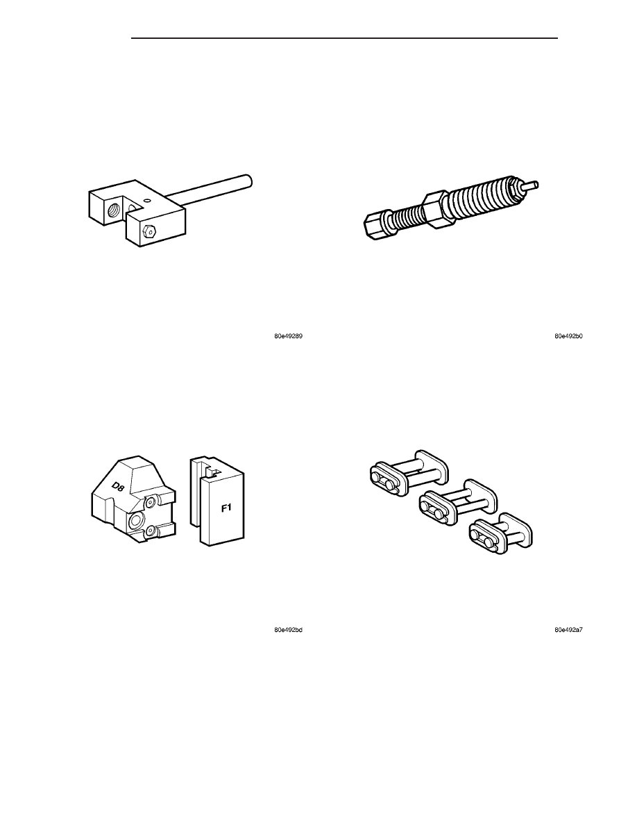
#8948 CHAIN SEPARATOR TOOL

#8949 THRUST PIECE

#8950 PRESSING SCREW

#8951 ASSEMBLY LINKS

9 - 16

ENGINE

PT

ENGINE - 2.2L DIESEL (Continued)

CYLINDER HEAD

STANDARD PROCEDURE

CYLINDER HEAD BOLT INSPECTION

(1) Measure cylinder head bolts between points

shown (Fig. 3).

Cylinder Head

Bolts

Thread

Diameter

12 M

Length When

New

102 mm

Maximum

Length

104 mm

(2) If the cylinder head bolt length is greater than

the maximum allowable measurement, replace the
cylinder head bolts.

MEASURE CYLINDER HEAD SURFACE

NOTE: Only resurface cylinder head contact surface
if porous or damaged. IT IS NOT necessary to
rework minor variations in flatness in the longitudi-
nal direction.

(1) Disconnect negative battery cable.
(2) Remove cylinder head (Refer to 9 - ENGINE/

CYLINDER HEAD - REMOVAL).

(3) Remove valves.
(4) Inspect cylinder head contact surface for flat-

ness, porous and damage.

(5) Using a straight edge, measure cylinder head

and cylinder block flatness.

(6) Measure cylinder head height at point (1) indi-

cated and retain reading (Fig. 4).

NOTE:

The

camshaft

housing

Must

Not

be

machined. Basic bore of the camshaft bearings will
be altered.

(7) Machine cylinder head contact surface, if nec-

essary.

(8) Measure cylinder head height (1) at point indi-

cated, record stock removal (Fig. 4).

(9) Measure valve setback at points (2) indicated

(Fig. 4).

NOTE: If measurement is less than dimension “2”
no further correct valve clearance compensation is
possible; replace valve seat ring or cylinder head if
measurement is greater than specification.

CYLINDER HEAD SPECIFICATIONS

Description

Specification

Height of Cylinder Head
(1), With Out Camshaft
Housing

126.85mm to 127.15mm

Valve Set Back (2) With
New Valves and New
Valve Seat Rings

Exhaust Valve: 1.0mm -

1.4mm

Intake Valve: 1.1mm -

1.5mm

#8952 ASSEMBLY INSERTS

Fig. 3 Measuring Cylinder Head Bolts

PT

ENGINE

9 - 17

ENGINE - 2.2L DIESEL (Continued)

REMOVAL

CYLINDER HEAD

(1) Disconnect negative battery cable located under

passenger seat (Fig. 5).

(2) Raise and support vehicle.
(3) Remove engine compartment lower silencer

and drive belt splash shield (Fig. 6).

WARNING: RISK OF INJURY TO SKIN AND EYES
FROM SCALDING COOLANT. DO NOT OPEN COOL-
ING SYSTEM UNLESS TEMPERATURE IS BELOW
90°C (194°F). OPEN CAP SLOWLY TO RELEASE
PRESSURE. STORE COOLANT IN APPROVED CON-
TAINER

ONLY.

WEAR

PROTECTIVE

GLOVES,

CLOTHING AND EYE WEAR.

(4) Drain cooling system (Refer to 7 - COOLING/

ENGINE/COOLANT - STANDARD PROCEDURE).

(5) Disconnect exhaust pipe from turbocharger

downpipe.

(6) Remove exhaust manifold support bracket (Fig.

7).

(7) Remove turbocharger support bracket (Fig. 7).
(8) Disconnect charge air cooler pipe from turbo-

charger.

(9) Disconnect oil return line from turbocharger.
(10) Remove starter and position out of the way.
(11) Remove accessory drive belt.
(12) Lower vehicle.
(13) Remove front grille assembly (Refer to 23 -

BODY/EXTERIOR/GRILLE - REMOVAL).

(14) Remove radiator closure panel (Refer to 23 -

BODY/EXTERIOR/RADIATOR

CROSSMEMBER

-

REMOVAL).

(15) Disconnect upper radiator hose from thermo-

stat housing.

(16) Pull cooling module forward to gain access to

the intake manifold inlet hose. Disconnect inlet hose
at manifold (Fig. 8).

(17) Remove engine cover. (Refer to 9 - ENGINE

COVER- REMOVAL).

Fig. 4 Cylinder Head Measurments

1 - CYLINDER HEAD HEIGHT
2 - VALVE SETBACK

Fig. 5 Battery Location

1 - BATTERY
2 - PASSENGER SEAT

Fig. 6 Engine Compartment Lower Silencer

1 - ENGINE COMPARTMENT SILENCER
2 - ACCESSORY DRIVE BELT SPLASH SHIELD

9 - 18

ENGINE

PT

CYLINDER HEAD (Continued)

(18) Remove air cleaner housing and turbocharger

inlet hose (Fig. 9)(Refer to 9 - ENGINE/AIR INTAKE
SYSTEM/AIR CLEANER HOUSING - REMOVAL).

(19) Remove coolant recovery pressure container-

.(Refer

to

7

-

COOLING/ENGINE/COOLANT

RECOVERY PRESS CONTAINER - REMOVAL)

(20) Disconnect

vacuum

hose

at

turbocharger

waste gate actuator.

WARNING: NO FIRE, OPEN FLAMES OR SMOKING.
RISK OF POISONING FROM INHALING AND SWAL-
LOWING FUEL. RISK OF INJURY FROM SKIN AND
EYE CONTACT WITH FUEL. POUR FUELS ONLY
INTO SUITABLE AND APPROPRIATELY MARKED
CONTAINERS.

WEAR

PROTECTIVE

CLOTHING

WHEN HANDLING FUEL.

(21) Disconnect fuel injector, glow plug, and cam-

shaft position sensor electrical connectors

(22) Remove fuel high pressure lines, return lines,

injectors, and fuel rail(Refer to 14 - FUEL SYSTEM/
FUEL INJECTION/FUEL INJECTOR - REMOVAL).

(23) Reposition wiring harness out of way.
(24) Remove cylinder head cover (Refer to 9 -

ENGINE/CYLINDER

HEAD/CYLINDER

HEAD

COVER(S) - REMOVAL).

(25) Position piston of cylinder #1 to ignition TDC.

Fig. 7 Turbo Support Bracket

1 - TURBO SUPPORT BRACKET
2 - EXHAUST MANIFOLD SUPPORT BRACKET
3 - EXHAUST MANIFOLD
4 - TURBOCHARGER
5 - TURBO OUTLET PIPE

Fig. 8 IntakeManifold

1 - INTAKE MANIFOLD
2 - INTAKE MANIFOLD RETAINING BOLTS
3 - INTAKE INLET HOSE

Fig. 9 Turbocharger Inlet Hose

1 - TURBOCHARGER INLET HOSE
2 - TURBOCHARGER

PT

ENGINE

9 - 19

CYLINDER HEAD (Continued)


Content   ..  203  204  205  206   ..