Chrysler Stratus Convertible. Manual - part 396


  Index      Chrysler     Chrysler Stratus Convertible - service repair manual 1995-2000 year


Search            


Content   ..  394  395  396  397   ..


Chrysler Stratus Convertible. Manual - part 396


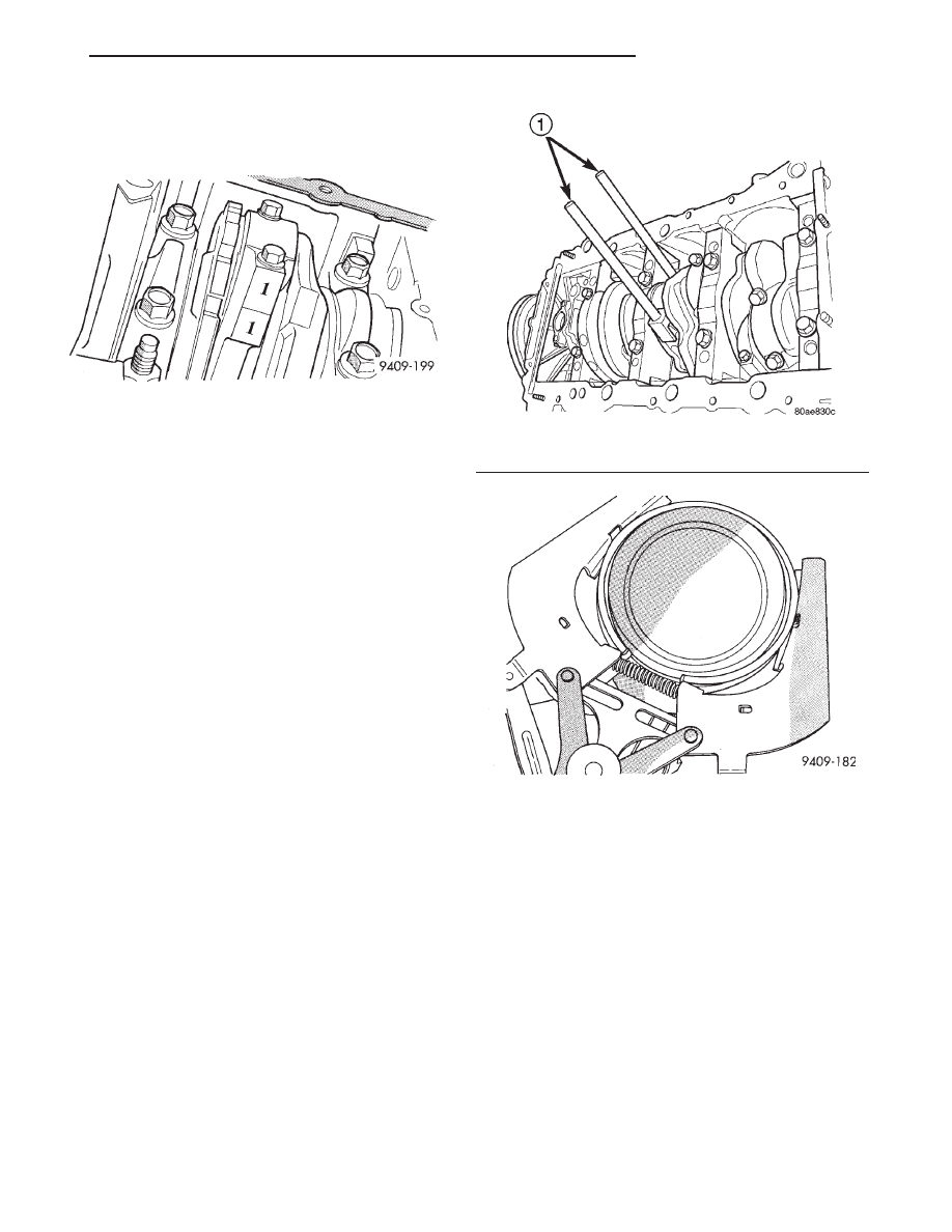
(3) Using a permanent ink marker or scribe tool

mark the cylinder number on the side of the rod and
cap (Fig. 119) for identification.

(4) Pistons will have a stamping in the approxi-

mate location shown in (Fig. 118). These stamps will
be either a directional arrow or a weight identifica-
tion for the assembly. L is for light and H is for
heavy. These assemblies should all be the same
weight class. Service piston assemblies are marked
with a S and can be used with either L or H produc-
tion assemblies. The weight designation stamps
should face toward the timing belt side of the engine.

(5) Pistons and connecting rods must be removed

from top of cylinder block. Rotate crankshaft so that
each connecting rod is centered in cylinder bore.

(6) Remove connecting rod cap bolts Do not use

old bolts if reinstalling connecting rod.

(7) To protect crankshaft journal and fractured rod

surfaces, install Special Tool 8189, connecting rod
guides onto connecting rod (Fig. 120). Carefully push
each piston and rod assembly out of cylinder bore.

CAUTION: Care must be taken not to damage the
fractured rod and cap joint surfaces, as engine
damage many occur.

(8) Remove Special Tool 8189, connecting rod

guides and re-install bearing cap on the mating rod.

NOTE: Piston and rods are serviced as an assem-
bly.

PISTON RING—REMOVAL

(1) The identification mark on face of upper and

intermediate piston rings must point toward piston
crown.

(2) Using a suitable ring expander, remove upper

and intermediate piston rings (Fig. 121).

(3) Remove the upper oil ring side rail, lower oil

ring side rail and then oil ring expander from piston.

(4) Clean ring grooves of any carbon deposits.

PISTON RINGS—INSTALLATION

(1) Install rings with manufacturers identification

mark facing up, to the top of the piston (Fig. 122).

CAUTION: Install

piston

rings

in

the

following

order:

a. Oil ring expander.
b. Upper oil ring side rail.
c. Lower oil ring side rail.
d. No. 2 Intermediate piston ring.
e. No. 1 Upper piston ring.
f. Install the side rail by placing one end between

the piston ring groove and the expander. Hold end
firmly and press down the portion to be installed
until side rail is in position. Do not use a piston
ring expander (Fig. 123).

(2) Install upper side rail first and then the lower

side rail.

Fig. 119 Identify Connecting Rod to Cylinder

Fig. 120 Connecting Rod Guides—Typical

1 – SPECIAL TOOL 8189 CONNECTING ROD GUIDES

Fig. 121 Piston Rings—Removing and Installing

JX

2.0L SOHC ENGINE

9 - 57

REMOVAL AND INSTALLATION (Continued)

(3) Install No. 2 piston ring and then No. 1 piston

ring (Fig. 122).

(4) Position piston ring end gaps as shown in (Fig.

124).

(5) Position oil ring expander gap at least 45° from

the side rail gaps but not on the piston pin center or
on the thrust direction. Staggering ring gap is impor-
tant for oil control.

PISTON AND ROD—INSTALLATION

(1) Before installing pistons and connecting rod

assemblies into the bore, be sure that compression
ring gaps are staggered so that neither is in line with
oil ring rail gap.

(2) Before installing the ring compressor, make

sure the oil ring expander ends are butted and the
rail gaps located as shown in (Fig. 124).

(3) Immerse the piston head and rings in clean

engine oil, slide the ring compressor, over the piston
(Fig. 125). Be sure position of rings does not
change during this operation
.

(4) The weight stamp designation L or H will be in

the front half of the piston should face toward the
front of the engine (Fig. 118).

(5) Rotate crankshaft so that the connecting rod

journal is on the center of the cylinder bore. Lubri-
cate connecting rod journal with clean engine oil.

(6) Position upper bearing half and install Special

Tool 8189, connecting rod guides onto connecting rod
(Fig. 120).

(7) Insert rod and piston assembly into cylinder

bore and carefully guide rod over the crankshaft jour-
nal.

Fig. 124 Piston Ring End Gap Position

1 – GAP OF LOWER SIDE RAIL
2 – NO. 1 RING GAP
3 – GAP OF UPPER SIDE RAIL
4 – NO. 2 RING GAP AND SPACER EXPANDER GAP

Fig. 125 Installing Piston

Fig. 122 Piston Ring Installation

1 – NO. 1 PISTON RING
2 – NO. 2 PISTON RING
3 – SIDE RAIL
4 – OIL RING
5 – SPACER EXPANDER

Fig. 123 Installing Side Rail

1 – SIDE RAIL END

9 - 58

2.0L SOHC ENGINE

JX

REMOVAL AND INSTALLATION (Continued)

(8) Tap the piston down in cylinder bore, using a

hammer handle. At the same time, guide connecting
rod into position on connecting rod journal.

(9) Remove Special Tool 8189, connecting rod

guides.

(10) Install connecting rod lower bearing half and

cap. Install New bolts and tighten to 27 N·m (20 ft.
lbs.) plus 1/4 turn.

(11) Install cylinder head and oil pan. Refer to pro-

cedures in this section.

DISASSEMBLY AND ASSEMBLY

OIL PUMP

(1) To remove the relief valve, proceed as follows:
(2) Remove the threaded plug and gasket from the

oil pump (Fig. 126).

CAUTION: Oil pump pressure relief valve must be
installed as shown in (Fig. 126) or serious damage
may occur.

(3) Remove spring and relief valve (Fig. 126).

(4) Remove oil pump cover screws, and lift off

cover.

(5) Remove pump rotors.
(6) Wash all parts in a suitable solvent and inspect

carefully for damage or wear (Fig. 127).

CLEANING AND INSPECTION

INTAKE MANIFOLD

CLEANING

Clean all mating surfaces.

INSPECTION

Inspect for:
• Cracked or distorted manifold.

• Damaged O-ring sealing surfaces on manifold

(Fig. 128).

Fig. 126 Oil Pressure Relief Valve

1 – RETAINER CAP
2 – GASKET
3 – OIL PUMP BODY
4 – RELIEF VALVE
5 – SPRING

Fig. 127 Oil Pump

1 – OIL PUMP BODY
2 – OIL PUMP COVER
3 – OUTER ROTOR
4 – INNER ROTOR

Fig. 128 Intake Manifold

1 – THROTTLE BODY TO MANIFOLD GASKET
2 – INJECTOR RAIL MOUNTS
3 – CAPTIVE O-RING GASKET

JX

2.0L SOHC ENGINE

9 - 59

REMOVAL AND INSTALLATION (Continued)

EXHAUST MANIFOLD

CLEANING

(1) Discard gasket and clean all surfaces of mani-

folds and cylinder head.

INSPECTION

(1) Inspect manifold gasket surfaces for flatness

with straight edge. Surface must be flat within 0.15
mm per 300 mm (0.006 in. per foot) of manifold
length.

(2) Inspect manifolds for cracks or distortion.

Replace manifold as necessary.

CYLINDER HEAD

CLEANING

Remove all gasket material from cylinder head. Be

careful not to gouge or scratch the aluminum head
sealing surface. Clean all engine oil passages.

To ensure engine gasket sealing, proper surface

preparation must be performed, especially with the
use of aluminum engine components and multi-layer
steel cylinder head gaskets.

Never use the following to clean aluminum gasket

surfaces:

• Metal scraper

• Abrasive pad or paper to clean cylinder block

and head

• High speed power tool with an abrasive pad or a

wire brush (Fig. 129)

NOTE: Multi-Layer

Steel

(MLS)

head

gaskets

require a scratch free sealing surface.

Only use the following for cleaning gasket surfaces:
• Solvent or a commercially available gasket

remover

• Plastic or wood scraper (Fig. 129)

• Drill motor with 3M Rolocy Bristle Disc (white

or yellow) (Fig. 129)

CAUTION: Excessive pressure or high RPM can
damage the sealing surfaces. The mild (white, 120
grit) bristle disc is recommended. If necessary, the
medium (yellow, 80 grit) bristle disc may be used
on cast iron surfaces with care.

INSPECTING CYLINDER HEAD

Check cylinder head for flatness with a straight

edge. Cylinder head must be flat within 0.1 mm
(0.004 in.) (Fig. 130).

Inspect cylinder head camshaft bearings for wear.

Check the camshaft journals for scratches and worn
areas. If light scratches are present, they may be
removed with 400 grit sand paper. If deep scratches

are present, replace the camshaft and check the cyl-
inder head for damage. Replace the cylinder head if
worn or damaged. Check the lobes for pitting and
wear. If the lobes show signs of wear, check the cor-
responding rocker arm roller for wear or damage.
Replace rocker arm/hydraulic lash adjuster if worn or
damaged. If lobes show signs of pitting on the nose,
flank or base circle; replace the camshaft.

Fig. 129 Proper Tool Usage For Surface Preparation

1 – ABRASIVE PAD
2 – 3M ROLOC

Y

BRISTLE DISC

3 – PLASTIC/WOOD SCRAPER

Fig. 130 Checking Cylinder Head Flatness

1 – FEELER GAUGE
2 – STRAIGHT EDGE

9 - 60

2.0L SOHC ENGINE

JX

CLEANING AND INSPECTION (Continued)


Content   ..  394  395  396  397   ..