Chrysler Stratus Convertible. Manual - part 394
 

  Index      Chrysler     Chrysler Stratus Convertible - service repair manual 1995-2000 year


Search            


Content   ..  392  393  394  395   ..


Chrysler Stratus Convertible. Manual - part 394


(4) Install timing belt and cover. Refer to proce-

dures in this section.

(5) Install crankshaft damper. Refer to procedure

in this section.

(6) Install accessory drive belts. Refer to COOL-

ING SYSTEM for procedure.

CRANKSHAFT OIL SEAL—REAR

REMOVAL

(1) Remove transaxle. Refer to TRANSAXLE for

procedure.

(2) Remove flex plate.
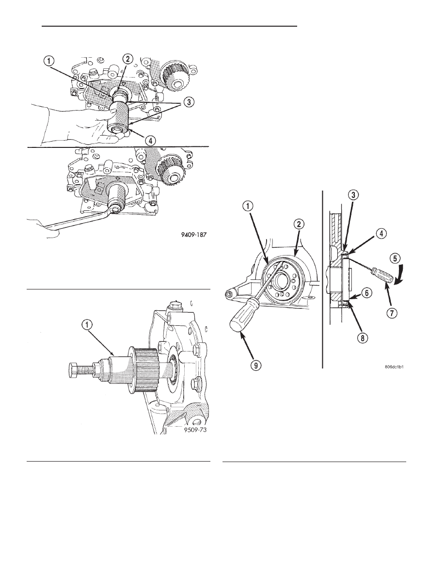
(3) Insert a 3/16 flat bladed screwdriver between

the dust lip and the metal case of the crankshaft
seal. Angle the screwdriver (Fig. 100) through the
dust lip against metal case of the seal. Pry out seal.

CAUTION: Do not permit the screwdriver blade to
contact crankshaft seal surface. Contact of the
screwdriver blade against crankshaft edge (cham-
fer) is permitted.

INSTALLATION

CAUTION: If burr or scratch is present on the
crankshaft edge (chamfer), cleanup with 400 grit
sand paper to prevent seal damage during installa-
tion of new seal.

Fig. 98 Front Crankshaft Oil Seal—Installation

1 – PROTECTOR
2 – SEAL
3 – SPECIAL TOOL 6780–1
4 – INSTALLER

Fig. 99 Crankshaft Sprocket—Installation

1 – SPECIAL TOOL 6792

Fig. 100 Rear Crankshaft Oil Seal—Removal

1 – REAR CRANKSHAFT SEAL
2 – ENGINE BLOCK
3 – ENGINE BLOCK
4 – REAR CRANKSHAFT SEAL METAL CASE
5 – PRY IN THIS DIRECTION
6 – CRANKSHAFT
7 – SCREWDRIVER
8 – REAR CRANKSHAFT SEAL DUST LIP
9 – SCREWDRIVER

JX

2.0L SOHC ENGINE

9 - 49

REMOVAL AND INSTALLATION (Continued)

NOTE: When installing seal, no lube on seal is
needed.

(1) Place Special Tool 6926-1 Seal Guide on crank-

shaft (Fig. 101).

(2) Position seal over guide tool (Fig. 101). Guide

tool should remain on crankshaft during installation
of seal. Ensure that the lip of the seal is facing
towards the crankcase during installation.

CAUTION: If the seal is driven into the block past
flush, this may cause an oil leak.

(3) Drive the seal into the block using Special Tool

6926-2 and handle C-4171 (Fig. 102) until the tool
bottoms out against the block (Fig. 103).

(4) Install flex plate. Apply Mopar

t Lock & Seal

Adhesive to bolt threads and tighten bolts to 95 N·m
(70 ft. lbs.).

(5) Install transaxle. Refer to TRANSAXLE for

procedure.

ENGINE CORE PLUGS

REMOVAL

Using a blunt tool such as a drift or a screwdriver

and a hammer, strike the bottom edge of the cup
plug (Fig. 104). With the cup plug rotated, grasp
firmly with pliers or other suitable tool and remove
plug (Fig. 104).

CAUTION: Do not drive cup plug into the casting
as restricted cooling can result and cause serious
engine problems.

Fig. 101 Rear Crankshaft Seal and Special Tool

6926-1

1 – SPECIAL TOOL 6926–1 PILOT
2 – SEAL

Fig. 102 Crankshaft Seal and Special Tools 6926-2 &

C-4171

1 – SPECIAL TOOL 6926–1 PILOT
2 – SEAL
3 – SPECIAL TOOL 6926–2 INSTALLER
4 – SPECIAL TOOL C-4171

9 - 50

2.0L SOHC ENGINE

JX

REMOVAL AND INSTALLATION (Continued)

INSTALLATION

Thoroughly clean all debris/rust from inside of cup

plug hole in cylinder block or head. Be sure to
remove old sealer. Lightly coat inside of cup plug hole
with Mopar

t Stud and Bearing Mount Adhesive.

Make certain the new plug is cleaned of all oil or
grease. Using a proper driver, drive plug into hole so
that the sharp edge of the plug is at least 0.5 mm
(0.020 inch.) inside the lead in chamfer (Fig. 104).

It is not necessary to wait for curing of the sealant.

The cooling system can be refilled and the vehicle
placed in service immediately.

CRANKSHAFT

REMOVAL

(1) Remove engine assembly. Refer to procedure in

this section.

(2) Mount engine on an engine stand.
(3) Remove oil filter and adapter from bedplate

(Fig. 105).

(4) Remove oil pan. Refer to procedure in this sec-

tion.

(5) Remove crankshaft sprocket and oil pump.

Refer to procedures in this section.

(6) Remove all bedplate bolts from the engine

block (Fig. 106).

(7) Using a mallet tap the bedplate loose from the

engine block dowel pins.

CAUTION: Do not pry up on one side of the bed-
plate. Damage may occur to cylinder block and bed-
plate alignment.

(8) Bedplate should be removed evenly from the

cylinder block dowel pins.

(9) Lift out crankshaft from cylinder block. Be sure

not to damage the main bearings or journals when
removing the crankshaft.

CRANKSHAFT MAIN BEARINGS LOCATION

The crankshaft is supported in five main bearings.

All upper bearing shells in the crankcase have oil
grooves. All lower bearing shells installed in the (bed-
plate) main bearing cap are plain. Crankshaft end
play is controlled by a flanged bearing on the number
three main bearing journal (Fig. 107).

NOTE: The upper and lower main Bearing shells
are Not interchangeable. The lower shells have a
revised tab to prevent improper installation.

Fig. 103 Rear Crankshaft Seal—Installation

1 – SPECIAL TOOL 6926–2 INSTALLER

Fig. 104 Core Hole Plug Removal

1 – CYLINDER BLOCK
2 – SECOND REMOVE PLUG WITH PLIERS
3 – FIRST STRIKE HERE WITH HAMMER
4 – DRIFT
5 – CUP PLUG

JX

2.0L SOHC ENGINE

9 - 51

REMOVAL AND INSTALLATION (Continued)

CRANKSHAFT MAIN JOURNALS INSPECTION

The crankshaft journals should be checked for

excessive wear, taper and scoring. Limits of taper or
out-of-round on any crankshaft journals should be
held to.025 mm (.001 inch). Journal grinding should
not exceed.305 mm (.012 inch) under the standard
journal diameter. DO NOT grind thrust faces of
Number 3 main bearing. DO NOT nick crank pin or
bearing fillets. After grinding, remove rough edges
from crankshaft oil holes and clean out all passages.

CAUTION: With the nodular cast iron crankshafts
used it is important that the final paper or cloth pol-
ish after any journal regrind be in the same direc-
tion as normal rotation in the engine.

Upper and lower Number 3 bearing halves are

flanged to carry the crankshaft thrust loads and are
NOT interchangeable with any other bearing halves

Fig. 105 Cylinder Block and Components

1 – OIL PASSAGE O-RING
2 – SEAL
3 – UPPER BEARING (GROOVED)
4 – THRUST BEARINGS
5 – BOLT
6 – O-RING
7 – NIPPLE

8 – OIL FILTER ADAPTER
9 – CRANKSHAFT POSITION SENSOR (CPS)
10 – MAIN BEARING CAP/BED PLATE ASSEMBLY
11 – CONNECTING ROD BEARINGS
12 – PISTON AND CONNECTING ROD ASSEMBLY
13 – SEAL

Fig. 106 Bedplate Bolts

9 - 52

2.0L SOHC ENGINE

JX

REMOVAL AND INSTALLATION (Continued)


Content   ..  392  393  394  395   ..