Chrysler Stratus Convertible. Manual - part 379


  Index      Chrysler     Chrysler Stratus Convertible - service repair manual 1995-2000 year


Search            


Content   ..  377  378  379  380   ..


Chrysler Stratus Convertible. Manual - part 379


INSPECTION

Check the oil filter mounting surface. The surface

must be smooth, flat and free of debris or old pieces
of rubber (Fig. 124). Check bracket for cracks and oil
leaks.

OIL PUMP

CLEANING

Disassemble oil pump and clean all components

using a suitable solvent.

INSPECTION

(1) Check oil pump case for damage and remove

rear cover.

(2) Remove pump rotors and inspect case for exces-

sive wear (Fig. 125).

(3) Insert the rotor into the oil pump case (Fig.

126) and measure clearance with a feeler gauge as
indicated. Replace if out of limits.

(4) Using

a

feeler

gauge,

measure

clearance

between inner rotor tip and outer rotor (Fig. 127).
Clearance specification is: 0.06 - 0.18 mm (0.0024 -
0.0071 in.). Replace if out of limits.

(5) Place a straightedge across face of pump hous-

ing (Fig. 128). Clearance should be between 0.04 -
0.10 mm (0.0015 - 0.0039 in.). Replace if out of limits.

OIL RELIEF PLUNGER

(1) Check

that

the

oil

relief

plunger

slides

smoothly (Fig. 125).

(2) Check for broken relief spring.

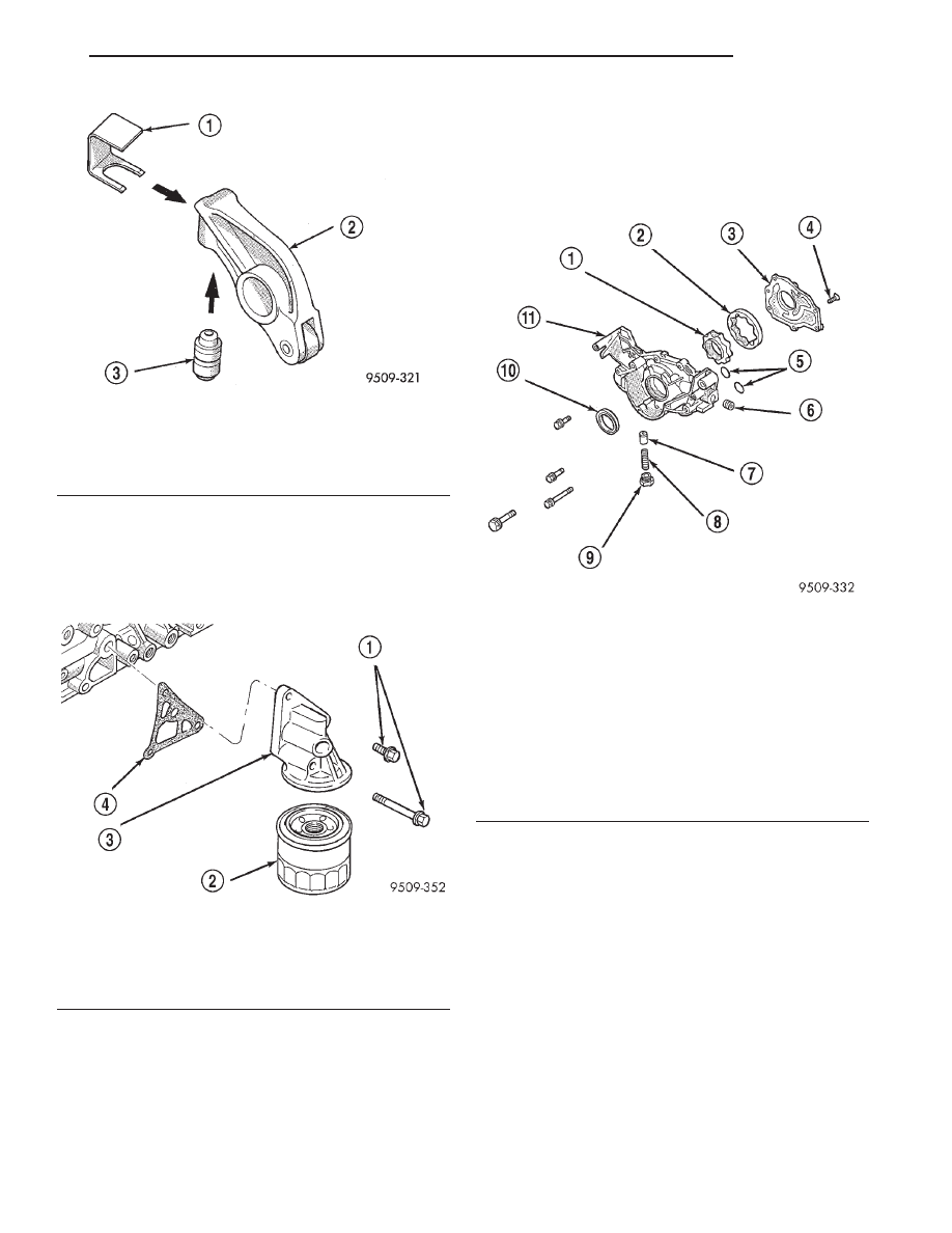
Fig. 123 Rocker Arm/Hydraulic Lash Adjuster

Assemblies

1 – SPECIAL TOOL MD998443
2 – ROLLER ROCKER ARM
3 – HYDRAULIC LASH ADJUSTER

Fig. 124 Oil Filter and Bracket

1 – 23 N·m (17 IN. LBS.)
2 – FILTER
3 – BRACKET
4 – GASKET

Fig. 125 Oil Pump Components

1 – INNER ROTOR
2 – OUTER ROTOR
3 – PUMP COVER
4 – SCREW
5 – O-RINGS
6 – PLUG
7 – OIL PRESSURE RELIEF VALVE
8 – RELIEF VALVE SPRING
9 – PLUG
10 – SEAL
11 – OIL PUMP BODY

JX

ENGINE

9 - 57

CLEANING AND INSPECTION (Continued)

OIL PUMP ASSEMBLY

(1) Assemble pump, using new parts as required

with clean oil. Align marks on the inner and outer
rotors when assembling (Fig. 129).

(2) Install cover and tighten screws to 12 N·m (105

in. lbs.)

(3) Install relief valve, spring, gasket and cap as

shown in (Fig. 125). Tighten cap to 41 N·m (30 ft.
lbs.)

TIMING BELT

CLEANING

Do Not attempt to clean a timing belt. If contami-

nation from oil, grease, or coolants have occurred, the
timing belt should be replaced.

Clean all sprockets using a suitable solvent. Clean

all sprocket grooves of any debris.

INSPECTION

(1) Remove the upper left timing belt cover (Fig.

130).

(2) Inspect both sides of the timing belt drive &

back. Replace belt if any of the following conditions
exist.

• Hardening of back rubber back side is glossy

without resilience and leaves no indent when pressed
with fingernail.

• Cracks on rubber back.

• Cracks or peeling of canvas.

• Cracks on rib root.

• Cracks on belt sides.

• Missing teeth.

• Contamination by oil, grease, or coolants.

• Abnormal wear of belt sides. The sides are nor-

mal if they are sharp as if cut by a knife (Fig. 131).

Fig. 126 Checking Clearance-Between Outer Rotor

and Case

1 – 0.10 TO 0.18 mm (0.004 TO 0.007 INCH)

Fig. 127 Measuring Clearance Between Rotors

Fig. 128 Measuring Clearance Over Rotors

Fig. 129 Inner and Outer Rotor Alignment Marks

1 – ALIGNMENT MARKS

9 - 58

ENGINE

JX

CLEANING AND INSPECTION (Continued)

(3) If none of the above conditions are seen on the

belt, the belt cover can be reinstalled.

VALVES, SPRINGS, SEATS AND GUIDES

CLEANING

Clean components using a suitable solvent.

INSPECTION

(1) Check valve stem tip for pitting or depression

at point A (Fig. 132).

(2) Check for wear and ridge wear at Point B.
(3) Measure the clearance between the valve guide

and valve stem. If the service limit is exceeded,
replace the valve guides, valves or both.

(4) Check for even contact (at face center) with

valve seat, Point C.

(5) Check margin. Refer to Engine Specifications.

Replace valve if margin is out of specification.

(6) Check valve guide height (Fig. 133).
(7) Measure valve stem to guide clearance. Refer

to Engine Specifications.

(8) Measure valve spring free length and if the

spring is square (Fig. 134). Refer to Engine Specifi-
cations.

Fig. 130 Timing Belt Covers

1 – UPPER RIGHT TIMING BELT COVER FASTENERS
2 – UPPER LEFT TIMING BELT COVER FASTENERS
3 – LOWER TIMING BELT COVER FASTENERS
4 – ENGINE BRACKET FASTENERS

Fig. 131 Timing Belt Inspection

1 – PEELING
2 – TOOTH MISSING AND CANVAS FIBER EXPOSED
3 – RUBBER EXPOSED
4 – CRACKS
5 – PEELING
6 – ROUNDED EDGE
7 – ABNORMAL WEAR (FLUFFY STRAND)

Fig. 132 Valve Inspection

1 – C IS A SEAT CONTACT MARK AND IS NOT FULL WIDTH OF

THE FACE

2 – MARGIN

JX

ENGINE

9 - 59

CLEANING AND INSPECTION (Continued)

VALVE SEAT INSPECTION

Inspect the valve seat with Prussian blue to deter-

mine where the valve contacts the seat. To do this,
coat valve seat LIGHTLY with Prussian blue then
set valve in place. Rotate the valve with light pres-
sure. If the blue is transferred to the center of valve
face, contact is satisfactory. If the blue is transferred
to top edge of the valve face, lower valve seat with a
15 degrees stone. If the blue is transferred to the bot-
tom edge of valve face raise valve seat with a 65
degree stone (Fig. 135).

ADJUSTMENTS

ENGINE SUPPORT ADJUSTMENT

The right and left support assemblies are slotted to

allow for right/left drive train adjustment in relation
to drive shaft assembly length.

Check and reposition right and left engine support

assemblies as required. Adjust drive train position, if
required, for the following conditions:

• Drive shaft distress: See Group 2, Suspension

and Driveshaft.

• Any front end structural damage (after repair).

• Support Assembly replacement.

ENGINE SUPPORT ADJUSTMENT

(1) Remove the load on the engine motor mounts

by carefully supporting the engine and transmission
assembly with a floor jack.

(2) Loosen the right engine support assembly ver-

tical fasteners.

(3) Loosen the left engine support assembly verti-

cal bolts.

(4) Pry the engine right or left as required to

achieve the proper drive shaft assembly length. Refer
to Group 2, Suspension and Driveshaft for driveshaft
identification and related assembly length measur-
ing.

(5) Tighten right engine support assembly vertical

bolts to 61 N·m (45 ft. lbs.). and tighten left engine
support assembly bolts to 61 N·m (45 ft. lbs.).

(6) Recheck drive shaft length.

Fig. 133 Valve Guide Height

Fig. 134 Valve Spring

1 – LENGTH

Fig. 135 Valve Seat Reconditioning

1 – EXHAUST
2 – INTAKE
3 – 0.9-1.3mm (.035-.051 IN.)
4 – 0.9-1.3mm (.035-.051 IN.)

9 - 60

ENGINE

JX

CLEANING AND INSPECTION (Continued)


Content   ..  377  378  379  380   ..