Chrysler Stratus Convertible. Manual - part 377
 

  Index      Chrysler     Chrysler Stratus Convertible - service repair manual 1995-2000 year


Search            


Content   ..  375  376  377  378   ..


Chrysler Stratus Convertible. Manual - part 377


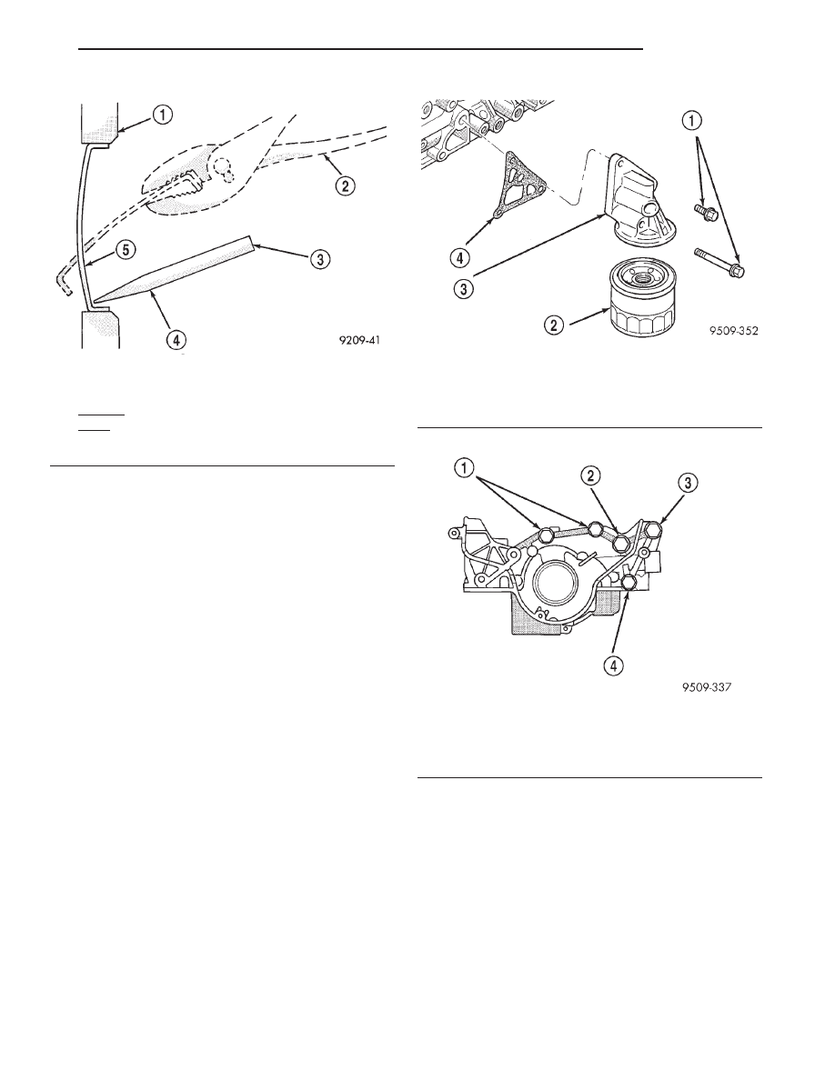
OIL FILTER

CAUTION: When servicing the oil filter (Fig. 96),
avoid deforming the filter can by installing the
remove/install tool band strap against the can-to-
base lock seam. The lock seam joining the can to
the base is reinforced by the base plate.

REMOVAL

(1) Turn filter counterclockwise to remove.

INSTALLATION

(1) Lubricate new filter gasket.
(2) Screw filter on until gasket contacts base.

Tighten to 14 N·m (10 ft. lbs.).

OIL PUMP

REMOVAL

(1) Remove accessory drive belts. Refer to Group 7,

Cooling System for procedure.

(2) Refer to procedures in this section for removing

the following components:

• Oil Pan

• Crankshaft Damper

• Timing Belt Covers

• Timing Belt
(3) Remove crankshaft sprocket and key.
(4) Remove oil pickup tube.
(5) Remove bolts that attach oil pump to block

(Fig. 97).

INSTALLATION

(1) Clean block and pump sealing surfaces.
(2) Prime oil pump before installation by filling

rotor cavity with clean engine oil.

(3) Apply Mopar

t Gasket Maker to oil pump as

shown in (Fig. 98). Install oil-ring into the counter
bore on the oil pump body discharge passage.

(4) Install oil pump slowly onto crankshaft until

seated to engine block. Tighten fasteners to M8 bolts
14 N·m (10 ft. lbs.) M10 bolts 41 N·m (30 ft. lbs.). See
(Fig. 97) for bolt location and length.

(5) Install oil pickup tube. Tighten fasteners to 19

N·m (168 in. lbs.).

Fig. 95 Core Hole Plug Removal

1 – CYLINDER BLOCK
2 – SECOND REMOVE PLUG WITH PLIERS
3 – FIRST STRIKE HERE WITH HAMMER
4 – DRIFT
5 – CUP PLUG

Fig. 96 Oil Filter and Bracket

1 – 23 N·m (17 IN. LBS.)
2 – FILTER
3 – BRACKET
4 – GASKET

Fig. 97 Oil Pump Assembly

1 – M8

3

25 MM (1 IN.)

2 – M8

3

30 MM (1 3/16 IN.)

3 – M10

3

50 MM (1 31/32 IN.)

4 – M8

3

60 MM (2 3/8 IN.)

JX

ENGINE

9 - 49

REMOVAL AND INSTALLATION (Continued)

(6) Install crankshaft sprocket and key.
(7) Refer to procedures in this section for installing

the following components:

• Timing Belt

• Timing Belt Covers

• Crankshaft Damper

• Oil Pan
(8) Install accessory drive belts. Refer to Group 7,

Cooling System for procedure.

PISTON AND CONNECTING ROD

REMOVAL

(1) Remove oil pan and cylinder head(s). Refer to

procedures in this section.

(2) Identify pistons with matching cylinder. The

pistons are not interchangeable from bank to
bank 
(Fig. 99). Pistons with the letter R and arrow
toward the front of engine are to be installed in cyl-
inders 1-3-5. Pistons with the letter L and arrow
toward the front of engine are to be installed in cyl-
inders 2-4-6.

(3) Mark connecting rod and cap with cylinder

number (Fig. 100).

(4) Remove piston rings (Fig. 101).

INSTALLING PISTON RINGS

(1) The No. 1 and No. 2 piston rings have a differ-

ent cross section. Install rings with manufacturers
mark and size mark facing up, to the top of the pis-
ton (Fig. 102).

CAUTION: Install

piston

rings

in

the

following

order:

a. Oil ring expander.
b. Upper oil ring side rail.
c. Lower oil ring side rail.
d. No. 2 Intermediate piston ring.
e. No. 1 Upper piston ring.
(2) Install the side rails (upper rail first, then

lower rail) by placing one end between the piston

Fig. 98 Oil Pump Sealing

1 – .118 in. (3 mm) OF SEALANT

Fig. 99 Piston Markings

1 – “L” FORWARD FOR CYLINDERS 2–4–6
2 – ARROW FACE TOWARD FRONT OF ENGINE

Fig. 100 Mark Matching Parts

1 – CYLINDER NUMBER

Fig. 101 Piston Ring—Removal

9 - 50

ENGINE

JX

REMOVAL AND INSTALLATION (Continued)

ring groove and the expander. Hold end firmly and
press down the portion to be installed until side rail
is in position. Do Not use a piston ring expander
(Fig. 103).

(3) Using a piston ring expander, install No. 2 pis-

ton ring and then No. 1 piston ring (Fig. 104).

(4) Position piston ring end gaps as shown in (Fig.

105).

(5) Position oil ring expander gap at least 45° from

the side rail gaps but not on the piston pin center or
on the thrust direction.

INSTALLATION

(1) Before installing pistons and connecting rod

assemblies into the bore, be sure that compression
ring gaps are staggered so that neither is in line with
oil ring rail gap.

(2) Before installing the ring compressor, make

sure the oil ring expander ends are butted and the
rail gaps located as shown in (Fig. 105).

(3) Immerse the piston head and rings in clean

engine oil, slide the ring compressor, over the piston
and tighten. Be sure position of rings does not
change during this operation.

(4) Install connecting rod bolt protectors on rod

bolts.

Fig. 102 Piston Ring—Installation

1 – NO. 1 PISTON RING
2 – NO. 2 PISTON RING
3 – SPACER EXTENDER
4 – OIL RING
5 – SIDE RAIL

Fig. 103 Side Rail—Installation

1 – SIDE RAIL END

Fig. 104 Upper and Intermediate Ring—Installation

1 – NO. 1 RING
2 – NO. 2 RING - INSTALL FIRST

Fig. 105 Piston Ring End Gap Position

1 – SIDE RAIL UPPER
2 – NO. 1 RING GAP
3 – PISTON PIN
4 – SIDE RAIL LOWER
5 – NO. 2 RING GAP AND SPACER EXPANDER GAP

JX

ENGINE

9 - 51

REMOVAL AND INSTALLATION (Continued)

(5) Rotate crankshaft so that the connecting rod

journal is on the center of the cylinder bore. Insert
rod and piston into cylinder bore and guide rod over
the crankshaft journal.

(6) Install the piston and connecting rod assembly

with the directional letter is located on the top of the
piston with the arrow facing toward the camshaft
sprocket.

(7) Tap the piston down in cylinder bore, using a

hammer handle. At the same time, guide connecting
rod into position on connecting rod journal (Fig. 106).

(8) Install rod caps. Install nuts on cleaned and

oiled rod bolts and tighten nuts to 52 N·m (38 ft. lbs.).

CAUTION: Piston assemblies are not to be inter-
changed from bank to bank.

(9) Check alignment marks made during disassem-

bly and that bearing position notches new or used
are on the same side as shown in (Fig. 107).

(10) Install cylinder head(s) and oil pan. Refer to

procedures in this section.

DISASSEMBLY AND ASSEMBLY

CYLINDER HEAD

DISASSEMBLY

CAUTION: Before disassembly, mark each valve’s
position on the face of each valve being removed.
The valves must be reinstalled into the same posi-
tion.

(1) With valve spring compressor Special Tool

C-3422-B with adapter 6526 or equivalent, remove
spring retainer locks, retainer, valve spring, and
valve (Fig. 108).

(2) Remove valve stem seals with suitable tool

(Fig. 109). Do not reuse valve stem seals.

ASSEMBLY

(1) Coat valve stems with clean engine oil and

insert valve in cylinder head in original position, if
being reused.

Fig. 106 Piston—Installation

Fig. 107 Connecting Rod and Cap

1 – CYLINDER NUMBER
2 – NOTCHES TO HOLD BEARING

Fig. 108 Valve Removal

1 – SPECIAL TOOL: C-3422–B
2 – SPECIAL TOOL: 6526

Fig. 109 Valve Stem Seals—Removal

1 – VALVE STEM SEAL

9 - 52

ENGINE

JX

REMOVAL AND INSTALLATION (Continued)


Content   ..  375  376  377  378   ..