Chrysler Stratus Convertible. Manual - part 244
 

  Index      Chrysler     Chrysler Stratus Convertible - service repair manual 1995-2000 year


Search            


Content   ..  242  243  244  245   ..


Chrysler Stratus Convertible. Manual - part 244


INSTRUMENT PANEL AND GAUGE

TABLE OF CONTENTS

page

page

DESCRIPTION AND OPERATION

ELECTRO/MECHANICAL INSTRUMENT

CLUSTER . . . . . . . . . . . . . . . . . . . . . . . . . . . . . . 1

DIAGNOSIS AND TESTING

HEADLAMP LEVELING SWITCH. . . . . . . . . . . . . . 1

REMOVAL AND INSTALLATION

FUEL GAUGE AND TEMPERATURE GAUGE . . . . . 2

HEADLAMP LEVELING SWITCH. . . . . . . . . . . . . . 3
SPEEDOMETER/TACHOMETER AND

ODOMETER TRANSMISSION RANGE
INDICATOR . . . . . . . . . . . . . . . . . . . . . . . . . . . . 4

DESCRIPTION AND OPERATION

ELECTRO/MECHANICAL INSTRUMENT
CLUSTER

The mechanical instrument cluster is an electro-

mechanical module which receives most of its infor-
mation from the Body Control Module (BCM) via the
CCD bus.

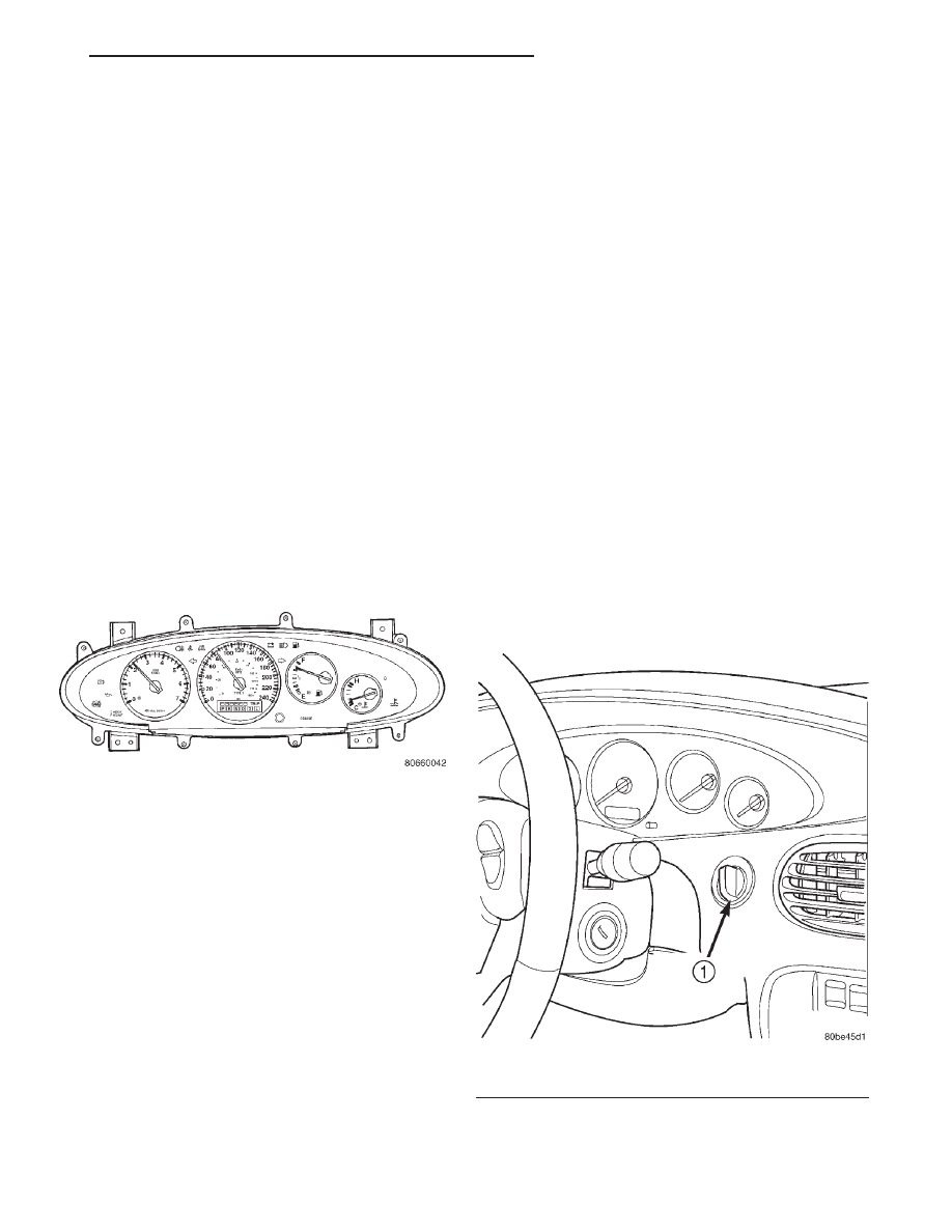
The cluster (Fig. 1) includes:

• 240 km/h (180 MPH) speedometer

• Tachometer

• Odometer/trip odometer and transmission range

indicator with automatic transmission

• Fuel gauge

• Temperature gauge

• Security alarm indicator (optional)
The warning and information indicators include

the following:

• Malfunction indicator lamp (Check Engine)

• Airbag

• Charging system

• Low oil pressure

• High temperature

• Low fuel

• Seat belt

• Cruise

• Brake/park brake

• Anti-lock brake system (optional)

• High beam

• Fog lamps (optional)

• Vehicle Theft Security System alarm LED indi-

cator (optional)

• Turn signals
The gauges are the magnetic air-core type. When

the ignition switch is OFF, the gauge pointers should
rest at or below the low graduation.

DIAGNOSIS AND TESTING

HEADLAMP LEVELING SWITCH

(1) Remove headlamp leveling switch from instru-

ment panel and disconnect the wire harness connec-

Fig. 1 Cluster

Fig. 2 Headlamp Leveling Switch Location

1 – HEADLAMP LEVELING SWITCH

JX

INSTRUMENT PANEL AND GAUGE

8E - 1

tor from the switch. Refer to Wiring Diagrams for the
proper wire circuits and connector connections.

(2) Using a voltmeter, connect B+ lead to Pin 1 of

the Wire harness connector. Connect the negative
lead to Pin 2. Turn ON the headlamp switch to the
low beam position. If battery voltage, OK. If not OK,
go to Step 3.

(3) Connect the ground lead to a good ground, if no

voltage, refer to Wiring Diagrams and test circuit
back to headlamp switch. If battery voltage, repair
Pin 2 ground circuit as necessary.

(4) Turn headlamps OFF. Connect the wire har-

ness connector to the headlamp leveling switch. Turn
ON the headlamp switch to the low beam position.
Check voltage at Pin 3, while rotating the headlamp
leveling switch knob through it’s range. The voltage
reading should change as the switch is rotated. If the
voltage does not vary replace switch. If OK, test the
headlamp leveling motors and/or circuit to the
motors.

REMOVAL AND INSTALLATION

FUEL GAUGE AND TEMPERATURE GAUGE

REMOVAL

(1) Disconnect and isolate the remote negative bat-

tery cable.

(2) Remove radio bezel. Refer to Group 23, Body

for procedure.

(3) Remove instrument panel cluster hood. Refer

to Group 23, Body for procedure.

(4) Remove

mask/lens

retaining

screws

and

remove mask/lens (Fig. 4).

(5) Disconnect odometer/transmission range indi-

cator connector from the printed circuit board (Fig.
5).

(6) Remove screws attaching speedometer/tachom-

eter to housing and remove.

(7) Remove the fuel/temperature gauge attaching

screws from the housing and remove (Fig. 6).

INSTALLATION

For installation, reverse the above procedures.

Fig. 3 Headlamp Leveling Switch Circuit Diagram

Fig. 4 Mask/Lens Retaining Screws

1 – MASK/LENS SCREWS
2 – CLUSTER SCREWS
3 – MASK/LENS SCREWS
4 – MASK/LENS SCREWS
5 – MASK/LENS SCREWS
6 – CLUSTER SCREWS
7 – MASK/LENS SCREWS
8 – MASK/LENS SCREWS

Fig. 5 Back Cover Retaining Screws

1 – CLUSTER BACK COVER RETAINING SCREWS
2 – ODOMETER/TRANSMISSION RANGE INDICATOR

CONNECTOR

3 – VTSS LED

8E - 2

INSTRUMENT PANEL AND GAUGE

JX

DIAGNOSIS AND TESTING (Continued)

HEADLAMP LEVELING SWITCH

REMOVAL

(1) Disconnect and isolate the battery negative

cable.

(2) Disconnect headlamp leveling switch electrical

connector and remove the instrument cluster hood
from the instrument panel. Refer to Group 23, Body
for the procedure.

(3) Remove the headlamp leveling switch from the

cluster hood by depressing the retaining tabs and
sliding out (Fig. 8).

INSTALLATION

(1) Connect headlamp leveling switch and verify

operation and disconnect switch.

(2) Install the instrument cluster hood on the

instrument panel. Be certain leveling switch wire
harness is inserted through hole in cluster hood.

(3) Connect headlamp leveling switch electrical

connector.

(4) Install leveling switch in cluster hood by push-

ing straight in (Fig. 9).

Fig. 6 Fuel Gauge and Temperature Gauge

Fig. 7 Headlamp Leveling Switch

1 – HEADLAMP LEVELING SWITCH

Fig. 8 Rear of Headlamp Leveling Switch

1 – REAR OF INSTRUMENT CLUSTER HOOD
2 – HEADLAMP LEVELING SWITCH
3 – SWITCH RETAINING TABS

Fig. 9 Headlamp Leveling Switch

1 – HEADLAMP LEVELING SWITCH

JX

INSTRUMENT PANEL AND GAUGE

8E - 3

REMOVAL AND INSTALLATION (Continued)

(5) Connect the negative battery cable.

SPEEDOMETER/TACHOMETER AND ODOMETER
TRANSMISSION RANGE INDICATOR

REMOVAL

(1) Disconnect and isolate the remote negative bat-

tery cable.

(2) Remove radio bezel. Refer to Group 23, Body

for procedure.

(3) Remove instrument panel cluster hood. Refer

to Group 23, Body for procedure.

(4) Remove

mask/lens

retaining

screws

and

remove mask/lens.

(5) Disconnect odometer/transmission range indi-

cator connector from the printed circuit board.

(6) Remove screws attaching speedometer/tachom-

eter to housing and remove.

(7) Remove screws attaching from the back of

speedometer and remove the odometer/transmission
range indicator display (Fig. 10).

INSTALLATION

For installation, reverse the above procedures.

Fig. 10 Odometer/Transmission Range Indicator

1 – MOUNTING SCREWS

8E - 4

INSTRUMENT PANEL AND GAUGE

JX

REMOVAL AND INSTALLATION (Continued)


Content   ..  242  243  244  245   ..