Chrysler Stratus Convertible. Manual - part 243


  Index      Chrysler     Chrysler Stratus Convertible - service repair manual 1995-2000 year


Search            


Content   ..  241  242  243  244   ..


Chrysler Stratus Convertible. Manual - part 243


(9) Open glove box door and press sidewalls

inboard while pulling the back panel rearward to
lower door from panel to access forward floor console.

(10) Remove forward floor console eight attaching

screws and one push pin at forward driver’s side.

(11) Disconnect Airbag Control Module (ACM) and

wiring connectors at center console.

(12) Pull the driver’s under panel silencer out-

board off the distribution duct.

(13) Remove left and right A-pillar moldings, start-

ing from the top edge and pulling them out.

(14) Remove instrument panel top cover attaching

screw on passenger side.

(a) Lift the right rear edge of top cover to disen-

gage the vertical clips along the rear edge. Pro-
ceeding from right to the left side. Do not use a
nylon trim stick, to avoid marring cover or panel.

(b) Lift rear edge and slide top cover rearward

disengaging angular clips and remove cover.

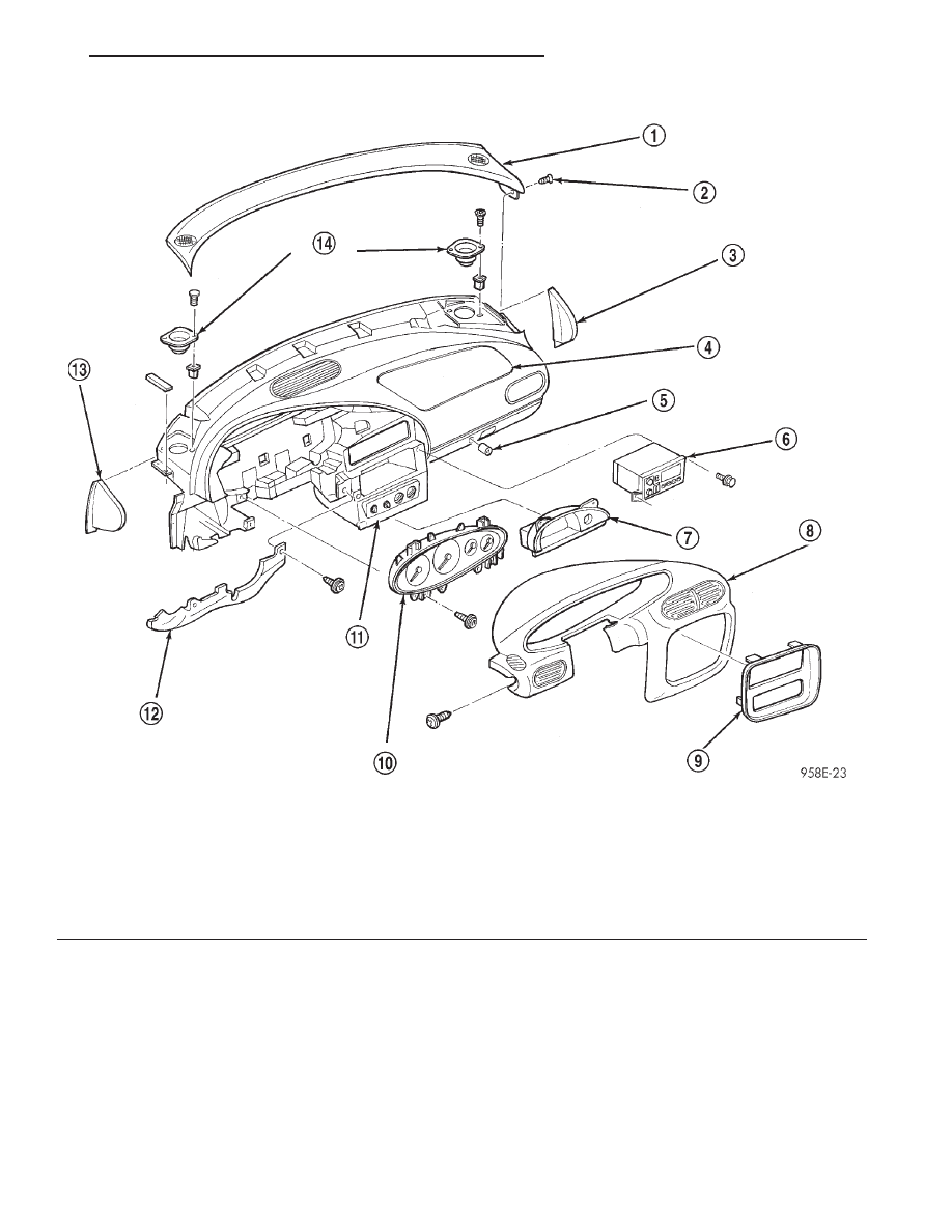
Fig. 17 Instrument Panel Breakdown

1 – TOP COVER
2 – SCREW
3 – END COVER
4 – PASSENGER AIRBAG MODULE
5 – GLOVE BOX LOCK CYLINDER
6 – RADIO
7 – CUBBY BIN

8 – INSTRUMENT CLUSTER HOOD
9 – CENTER BEZEL
10 – INSTRUMENT CLUSTER
11 – HVAC
12 – KNEE BOLSTER
13 – END COVER
14 – SPEAKERS

JX

INSTRUMENT PANEL SYSTEMS

8E - 11

REMOVAL AND INSTALLATION (Continued)

(15) Remove HVAC control attaching screws.
(16) Disconnect wire harness connectors and con-

trol cables from HVAC control head.

(17) Remove center distribution duct screws from

behind radio and duct.

(18) Remove radio. Access and remove the three

HVAC attaching screws to duct and panel. Remove
the three HVAC attaching bolts from the cross-car
beam.

(19) Close glove box door.
(20) Remove five screws attaching panel to ple-

num.

(21) Remove steering column shrouds.
(22) Disconnect steering column wiring connectors.
(23) Disconnect shift interlock cable.
(24) Remove four steering column retaining nuts

and lower column to floor.

(25) Disconnect engine and body wire harness

from Junction Block/BCM.

(26) Remove one push pin to right underpanel

silencer.

(27) Remove fasteners:
• Four at left end and three at the right end of the

cross car beam

• Two at steering column plenum

• One at glove box hinge to A-pillar

• Two at center support to the floor pan bracket
(28) Remove attaching screw at the rear of HVAC

to the center support bracket.

(29) With the help of an assistant, lift up instru-

ment panel and move rearward to remove.

INSTALLATION

For installation, reverse the above procedures. DO

NOT CONNECT battery negative remote cable. Refer
to Group 8M, Restraint Systems for Air Bag System
test.

INSTRUMENT PANEL END COVERS – LEFT
AND RIGHT

REMOVAL

(1) Open the left door and pull on the access han-

dle and pivoting around A-pillar to disengage end
cover clips. Fuse Puller, Spare Fuses And Fuse Dia-
gram Are Located On Left End Cover. Fuse Access Is
Under Left End Cover (Fig. 17).

(2) Open right door and glove box door.
(3) Remove right end cover by pulling rearward to

disengage clips.

INSTALLATION

For installation, reverse the above procedures.

Ensure spare fuses are seated to left end cover.

INSTRUMENT PANEL SPEAKERS

REMOVAL

(1) Disconnect and isolate the battery negative

remote cable (Fig. 11).

(2) Remove instrument panel top cover, refer to

Instrument Panel Top Cover Removal and Installa-
tion in this section.

(3) Remove two screws on each speaker and lift

up, disconnect wiring connector and remove speaker.

INSTALLATION

For installation, reverse the above procedures

INSTRUMENT PANEL TOP COVER

REMOVAL

(1) Open glove box door.
(2) Remove right end cap and remove screw at

right end.

(3) Using a trim stick (special tool #C-4655), gently

pry out and remove both left and right A-pillar trim
moldings.

(4) Lift the right rear edge of top cover to disen-

gage the clips along the rear edge. Proceeding from
right to the left side. Do not use a nylon trim stick,
to avoid potential damage (Fig. 18).

(5) Lift rear edge and slide top cover rearward dis-

engaging clips and remove cover.

INSTALLATION

For installation, reverse the above procedures.

Ensure the two center clips are engaged first. Place
thumb in VIN opening and pull towards pad to
ensure VIN alignment. If a gap exist between the top
cover and pad after installation check for a damaged
clip. The clip must be removed and replaced.

Fig. 18 Instrument Panel Top Cover

1 – SPEAKER

8E - 12

INSTRUMENT PANEL SYSTEMS

JX

REMOVAL AND INSTALLATION (Continued)

LEFT UNDER INSTRUMENT PANEL SILENCER/
DUCT

REMOVAL

(1) Remove two lower knee bolster screws and slip

silencer off outboard attaching formation.

(2) Maneuver part off of center floor distribution

duct to remove.

INSTALLATION

For installation, reverse the above procedures.

Install prior to knee bolster.

MASK/LENS

REMOVAL

(1) Remove Cluster Hood. Refer to Cluster Hood

Removal and Installation in this section.

Remove mask/lens retaining screws and remove

mask/lens (Fig. 13).

INSTALLATION

For installation, reverse the above procedures.

ODOMETER/TRANSMISSION RANGE
INDICATOR

The Instrument Cluster must be removed to ser-

vice the Odometer/Transmission Range Indicator.
Refer to Instrument Cluster Removal and Installa-
tion in this section.

REMOVAL

(1) Remove

Speedometer/Tachometer,

Refer

to

Speedometer/Tachometer

and

Odometer/Transmis-

sion Range Indicator Removal and Installation in
this section.

(2) Remove screws attaching from the back of

speedometer and remove the odometer/transmission
range indicator display (Fig. 19).

INSTALLATION

For installation, reverse the above procedures.

RADIO

For Radio Removal and Installation, Refer to

Group 8F, Audio Systems.

RIGHT UNDER INSTRUMENT PANEL
SILENCER/DUCT

REMOVAL

(1) Remove two push-in fasteners under right end

of instrument panel.

(2) Maneuver part off center floor distribution duct

to remove.

INSTALLATION

For installation, reverse the above procedures.

SPEEDOMETER, TACHOMETER, ODOMETER,
AND TRANSMISSION RANGE INDICATOR

The Instrument Cluster must be removed to ser-

vice the speedometer-tachometer-odometer and trans-
mission range indicator. Refer to Instrument Cluster
Removal and Installation in this section.

REMOVAL

(1) Remove

mask/lens

retaining

screws

and

remove mask/lens (Fig. 13).

(2) Disconnect odometer / transmission range indi-

cator connector from the printed circuit board (Fig.
14).

(3) Remove screws attaching speedometer / tach-

ometer to housing and remove (Fig. 15).

(4) Remove screws attaching from the back of

speedometer and remove the odometer / transmission
range indicator display (Fig. 19).

INSTALLATION

For installation, reverse the above procedures.

TRACTION CONTROL SWITCH

The Traction Control Switch is located within the

instrument cluster hood, just to the right of the
steering column (Fig. 20).

REMOVAL

(1) Disconnect and isolate the battery negative

remote cable (Fig. 11).

(2) Using a trim stick (special tool #C-4755) or

suitable tool, gently pry out on traction control
switch and remove it from instrument cluster hood.

(3) Disconnect harness connector from Traction

Control Switch.

INSTALLATION

For installation, reverse the above procedures.

Fig. 19 Odometer/Transmission Range Indicator

1 – MOUNTING SCREWS

JX

INSTRUMENT PANEL SYSTEMS

8E - 13

REMOVAL AND INSTALLATION (Continued)

VEHICLE THEFT/SECURITY SYSTEM LED

The Instrument Cluster must be removed to ser-

vice the Vehicle Theft/Security System LED. Refer to

Instrument Cluster Removal and Installation in this
section.

REMOVAL

(1) Disconnect Vehicle Theft / Security System

LED socket assembly from the printed circuit board
(Fig. 9).

(2) Rotate

LED

socket

counter

clockwise

and

remove from printed circuit board.

INSTALLATION

For installation, reverse the above procedures.

Fig. 20 Traction Control Switch Location

1 – TRACTION CONTROL SWITCH

8E - 14

INSTRUMENT PANEL SYSTEMS

JX

REMOVAL AND INSTALLATION (Continued)


Content   ..  241  242  243  244   ..