Chrysler Stratus Convertible. Manual - part 209
(3) Tighten the 3 HCU mounting bolts to a torque
of 11 N·m (97 in. lbs.).
CAUTION: Before installing the 25-way connector
in the CAB be sure that the seal is properly
installed in the connector.
(4) Install the 25-way connector into the socket on
the CAB. The connector is installed using the follow-
ing procedure. Position the 25-way connector in the
socket on the CAB and carefully push it down as far
as it will go. When connector is fully seated into the
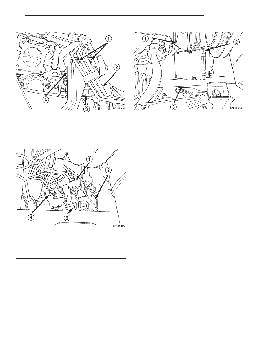
CAB socket push in the connector lock (Fig. 35) as
far as it will go. This will pull the 25-way connector
into the socket on the CAB and lock it in the
installed position.
(5) Install the 2 bolts (Fig. 32) attaching the back
legs of the HCU mounting bracket to the front sus-
pension crossmember.
(6) Install the bolt (Fig. 31) attaching the front leg
of the HCU mounting bracket to the front suspension
crossmember.
(7) Tighten the 3 bolts mounting the HCU mount-
ing to the front suspension crossmember to a torque
of 28 N·m (250 in. lbs.).
(8) Install the primary and secondary brake tubes
coming from the master cylinder in the HCU inlet
ports (Fig. 30).
(9) Install the 4 chassis brake tubes in the outlet
ports on the HCU (Fig. 29).
(10) Using a crow foot (Fig. 37) and (Fig. 38)
tighten all of the brake tube nuts to a torque of 17
N·m (145 in. lbs.).
(11) Install the HCU heat shield (Fig. 28) on the
HCU mounting bracket. Install and securely tighten
the attaching bolt.
(12) Install exhaust system in vehicle using the
reverse steps of its removal.
(13) Install right side engine compartment splash
shield (Fig. 25) back on the vehicle.
(14) Lower vehicle.
(15) Remove brake pedal holding tool.
(16) Install the remote ground cable onto the
ground stud located on left shock tower (Fig. 22).
Install the remote ground cable attaching nut and
tighten to a torque of 28 N·m (250 in. lbs.).
Fig. 34 HCU To Bracket Mounting Bolt
1 – MOUNTING BOLTS
2 – FUEL LINES
3 – HCU
4 – HCU MOUNTING BRACKET
Fig. 35 Unlocked CAB Connector
1 – CONNECTOR LOCK
2 – CAB CONNECTOR
3 – CAB
4 – HCU
Fig. 36 ICU Remove And Install
1 – FRAME RAIL
2 – HCU
3 – DRIVESHAFT
JX
BRAKES
5 - 99
REMOVAL AND INSTALLATION (Continued)