Chrysler Stratus Convertible. Manual - part 154


  Index      Chrysler     Chrysler Stratus Convertible - service repair manual 1995-2000 year


Search            


Content   ..  152  153  154  155   ..


Chrysler Stratus Convertible. Manual - part 154


REMOVAL AND INSTALLATION

SAFETY PRECAUTIONS AND WARNINGS

WARNING: WEAR EYE PROTECTION WHEN SER-
VICING THE AIR CONDITIONING REFRIGERANT
SYSTEM. SERIOUS EYE INJURY CAN RESULT
FROM EYE CONTACT WITH REFRIGERANT. IF EYE
CONTACT IS MADE, SEEK MEDICAL ATTENTION
IMMEDIATELY.

DO

NOT

EXPOSE

REFRIGERANT

TO

OPEN

FLAME. POISONOUS GAS IS CREATED WHEN
REFRIGERANT IS BURNED. AN ELECTRONIC TYPE
LEAK DETECTOR IS RECOMMENDED.

LARGE AMOUNTS OF REFRIGERANT RELEASED

IN A CLOSED WORK AREA WILL DISPLACE THE
OXYGEN AND CAUSE SUFFOCATION.

THE EVAPORATION RATE OF REFRIGERANT AT

AVERAGE

TEMPERATURE

AND

ALTITUDE

IS

EXTREMELY HIGH. AS A RESULT, ANYTHING THAT
COMES IN CONTACT WITH THE REFRIGERANT
WILL FREEZE. ALWAYS PROTECT SKIN OR DELI-
CATE OBJECTS FROM DIRECT CONTACT WITH
REFRIGERANT. R-134a SERVICE EQUIPMENT OR
VEHICLE A/C SYSTEM SHOULD NOT BE PRES-
SURE TESTED OR LEAK TESTED WITH COM-
PRESSED AIR.

SOME MIXTURES OF AIR and R-134a HAVE BEEN

SHOWN

TO

BE

COMBUSTIBLE

AT

ELEVATED

PRESSURES. THESE MIXTURES ARE POTENTIALLY
DANGEROUS AND

MAY

RESULT

IN

FIRE

OR

EXPLOSION

CAUSING

INJURY

OR

PROPERTY

DAMAGE.

ANTIFREEZE IS AN ETHYLENE GLYCOL BASE

COOLANT AND IS HARMFUL IF SWALLOWED OR
INHALED. SEEK MEDICAL ATTENTION IMMEDI-
ATELY IF SWALLOWED OR INHALED. DO NOT
STORE IN OPEN OR UNMARKED CONTAINERS.
WASH SKIN AND CLOTHING THOROUGHLY AFTER
COMING IN CONTACT WITH ETHYLENE GLYCOL.
KEEP OUT OF REACH OF CHILDREN AND PETS.

DO NOT OPEN A COOLING SYSTEM WHEN THE

ENGINE IS AT RUNNING TEMPERATURE. PER-
SONAL INJURY CAN RESULT.

CAUTION: The engine cooling system is designed
to develop internal pressure of 97 to 123 kPa (14 to
18 psi). Allow the vehicle to cool a minimum of 15
minutes before opening the cooling system. Refer
to Group 7, Cooling System.

A/C PRESSURE TRANSDUCER

CAUTION: A/C pressure transducer switch connec-
tor terminal contacts can be damaged by probing

tools during system diagnosis and repair. Failure to
use their respective mating terminals or pin gauge
to check for tightness will cause contact beam
spreads. This will result in loss of continuity.

NOTE: O-ring replacement is required whenever the
pressure transducer is serviced. Be sure to use the
O-ring specified for this vehicle.

REMOVAL

(1) If equipped with a 2.4L engine, hoist vehicle.
(2) Disconnect the wire harness connector from the

A/C pressure transducer.

NOTE: A slight release of pressure trapped in the
fitting may be experienced. It is not necessary to
discharge the refrigerant system.

(3) Remove the transducer with a counterclockwise

rotation using a 14 mm open-end wrench (Fig. 8) and
(Fig. 9).

INSTALLATION

For installation, reverse above procedures. Tighten

pressure transducer to 6 N·m (50 in. lbs.).

BLOWER MOTOR AND WHEEL ASSEMBLY

The blower motor is located on the right side of the

heater housing.

REMOVAL

(1) Disconnect battery.
(2) Remove lower right under panel silencer duct.

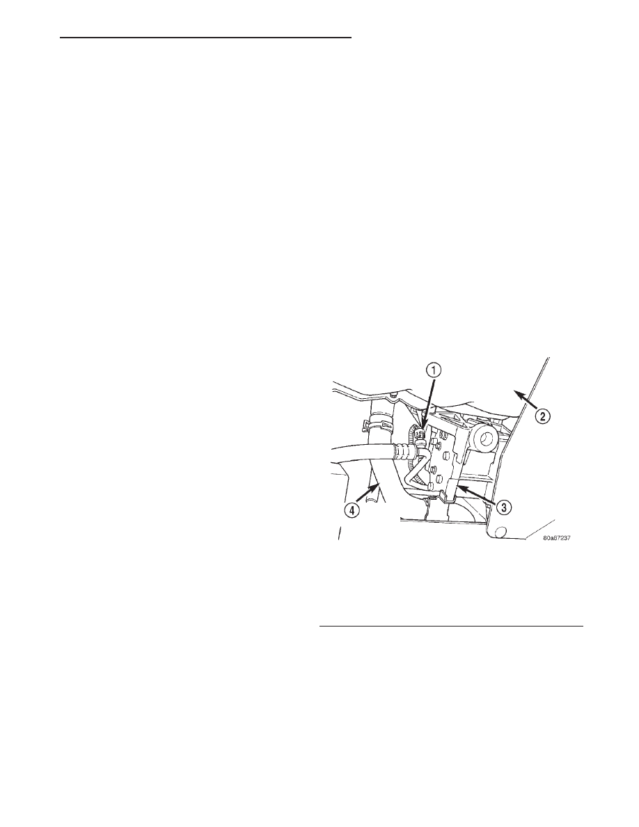
Fig. 8 Pressure Transducer (2.4L engine, viewed

from beneath vehicle)

1 – A/C PRESSURE TRANSDUCER
2 – OIL PAN
3 – A/C COMPRESSOR
4 – LOWER RADIATOR HOSE

JX

HEATING AND AIR CONDITIONING

24 - 13

(3) Remove blower motor connector from resistor

block (Fig. 10).

(4) Remove blower motor case retaining screws.
(5) Lower

blower

motor

case

from

housing

(Fig. 11).

(6) Remove fan scroll from motor shaft.
(7) Remove motor from motor case.

INSTALLATION

For installation, reverse the above procedures.

BLOWER MOTOR RESISTOR

The blower motor resistor is located on the lower

right side of the heater housing.

REMOVAL

(1) Remove lower right underpanel silencer/duct.

(2) Disconnect wiring connectors on blower motor

resistor.

(3) Remove blower motor resistor retaining screws.
(4) Pull blower motor resistor out of heater hous-

ing (Fig. 12).

INSTALLATION

For installation, reverse the above procedures.

BLOWER MOTOR WHEEL

The blower motor wheel is only serviced with the

blower motor. The wheel and the motor are balanced
as an assembly. If the blower motor wheel requires
replacement, the blower motor must also be replaced.
Refer to blower motor for replacement procedure.

Fig. 9 Pressure Transducer (2.5L engine)

1 – A/C PRESSURE TRANSDUCER

Fig. 10 Blower Motor Wiring

1 – BLOWER MOTOR
2 – BLOWER MOTOR WIRING

Fig. 11 Blower Motor

1 – BLOWER MOTOR

Fig. 12 Blower Motor Resistor

1 – A/C HOUSING
2 – BLOWER MOTOR RESISTOR

24 - 14

HEATING AND AIR CONDITIONING

JX

REMOVAL AND INSTALLATION (Continued)

COMPRESSOR

REMOVAL

(1) Disconnect the battery negative remote cable.
(2) Loosen and remove drive belt (Fig. 13). Refer to

Group 7, Engine Cooling.

(3) Disconnect compressor clutch wire lead.
(4) Recover refrigerant system with R-134a recov-

ery unit.

(5) Remove

refrigerant

lines

from

compressor

(Fig. 14).

(6) Remove compressor attaching bolts (Fig. 15)

and (Fig. 16).

(7) Remove compressor (Fig. 17).

INSTALLATION

(1) Position the compressor on the mount.
(2) Install the compressor attaching bolts. Tighten

bolts to 41 N·m (30 ft. lbs.) torque.

(3) Install drive belt (refer to Group 7, Cooling

System).

(4) Install refrigerant hoses and new seals.
(5) Connect the clutch wire.
(6) Charge the system.
(7) Connect the negative cable to the battery.

Fig. 13 Drive Belt

1 – DRIVE BELT
2 – A/C COMPRESSOR

Fig. 14 A/C Lines

1 – SUCTION PORT
2 – DISCHARGE PORT

Fig. 15 Lower Attaching Bolts

1 – LOWER MOUNTING BOLTS

Fig. 16 Upper Attaching Bolts

1 – UPPER MOUNTING BOLTS

JX

HEATING AND AIR CONDITIONING

24 - 15

REMOVAL AND INSTALLATION (Continued)

COMPRESSOR CLUTCH/COIL ASSEMBLY

REMOVAL

(1) Remove the compressor from the mount.
(2) Install two (6 mm) bolts into the threaded

holes in the armature plate. Hold bolts with two
wrenches to prevent shaft from turning (Fig. 18).
Remove compressor shaft nut.

(3) Lightly tap clutch plate with a plastic hammer

and remove plate and shim(s) (Fig. 19).

CAUTION: Do not use screwdrivers between the
armature plate assembly and rotor-pulley to remove
the armature plate. This may damage the armature
plate assembly.

(4) Remove pulley retaining snap ring with snap

ring pliers. Remove pulley assembly from compressor.
Use a plastic hammer, if necessary.

(5) Loosen the lead wire retaining clamps and

remove lead wire from the compressor front end
cover. Disconnect the lead wire from the thermal lim-
iter switch.

(6) Remove snap ring which secures field coil-core

assembly to the front cover (Fig. 19). Note the align-
ment of field coil-core assembly when removing.

WARNING: TAKE CARE THAT THE SNAP RING
DOES NOT FLY OUT FROM THE GROOVE.

INSPECTION

Examine frictional faces of the rotor-pulley and

armature plate for wear. The pulley and plate should
be replaced if there is excessive wear or scoring. If
the friction surfaces are oily, inspect the shaft nose
area of the compressor for excess oil. If excess oil is
present, the shaft seal is leaking and the compressor
must be replaced.

Check pulley hub bearing for roughness or exces-

sive grease leakage. Check for bearing grease con-
tamination on armature plate faces.

CAUTION: The pulley and clutch plate were mated
at the factory by a burnishing operation. No attempt
should be made to separately replace either part.
This will result in clutch slippage due to insufficient
contact area.

Fig. 17 Compressor Removal

1 – COMPRESSOR

Fig. 18 Compressor Shaft Nut Removal/Installation

1 – BOLTS
2 – BOX-END WRENCHES
3 – ARMATURE PLATE

Fig. 19 Clutch Plate/Pulley/Field Coil

1 – FIELD COIL-CORE
2 – ROTOR-PULLEY
3 – ARMATURE PLATE

24 - 16

HEATING AND AIR CONDITIONING

JX

REMOVAL AND INSTALLATION (Continued)


Content   ..  152  153  154  155   ..