Chrysler Stratus Convertible. Manual - part 111
SYNCHRONIZER
DISASSEMBLY
Place synchronizer in a clean shop towel and wrap.
Press on inner hub. Carefully open up shop towel
and remove springs, balls, keys, hub, and sleeve.
ASSEMBLY
(1) Position synchronizer hub onto a suitable hold-
ing fixture (input shaft). The synchronizer hubs are
directional. The hubs must be installed with the U
facing upward.
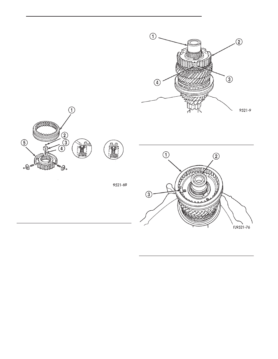
(2) Install springs into hub slot (Fig. 120).
(3) Insert key into hub and spring.
(4) Apply petroleum jelly to the hole in the key.
Insert balls into each key (Fig. 121).
(5) Slide sleeve over the hub and depress balls as
you carefully slip the sleeve into position (Fig. 122).
(6) Line up stop ring tang over the keys in the hub
(Fig. 123). Install stop rings. Center the keys and
balls by pushing on both stop rings.
SHIFT RAILS OVERHAUL
(1) Remove shift rails from the geartrain.
(2) To service the 5-R shift rail, remove the C-clip
retaining the reverse shift lever arm. Remove the 5th
shift fork roll pin and remove the 5th shift fork.
Remove the shift lug roll pin and remove the shift
lug. Replace parts as necessary.
(3) To service the 3-4 shift rail, remove the roll pin
retaining the 3-4 shift fork. Remove the shift fork.
Remove the shift lug roll pin and remove the shift
lug. Replace parts as necessary.
(4) To service the 1-2 shift rail, remove the roll pin
retaining the 1-2 shift fork. Remove the shift fork
and replace parts as necessary.
Fig. 120 Synchronizer Assembly
1 – SLEEVE
2 – BALL
3 – KEY
4 – SPRING
5 – HUB
Fig. 121 Synchronizer Balls
1 – INPUT SHAFT
2 – HUB
3 – KEY
4 – BALL
Fig. 122 Synchronizer Sleeve
1 – SLEEVE
2 – INPUT SHAFT
3 – KEY
JX
TRANSAXLE
21 - 35
DISASSEMBLY AND ASSEMBLY (Continued)