Chrysler Stratus Convertible. Manual - part 110
RING GEAR
CAUTION: Always
install
new
ring
gear
bolts.
Tighten ring gear bolts to 81 N·m (60 ft. lbs.) torque.
SPEEDOMETER DRIVE GEAR
NOTE: The plastic speedometer drive gear must be
removed from the differential case in order to ser-
vice the differential gears
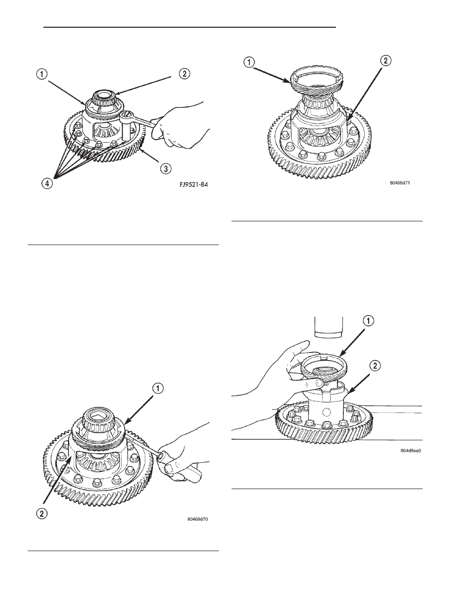
REMOVAL
(1) Pry the plastic speedometer drive gear off of
the differential case using a flat blade pry tool (Fig.
106) (Fig. 107).
INSTALLATION
NOTE: A new speedometer drive gear must be
installed on differential assembly. The lip on the
speedometer drive gear must be positioned down-
ward when installing onto differential assembly.
(1) Position speedometer drive gear onto differen-
tial assembly (Fig. 108).
(2) Using Miller Tool # L-4440 and steel stock,
press speedometer drive gear onto differential (Fig.
109) (Fig. 110). Do not use a hammer.
Fig. 105 Remove or Install Ring Gear Bolts and
Ring Gear
1 – SPEEDOMETER DRIVE GEAR
2 – BEARING
3 – RING GEAR
4 – RING GEAR BOLTS
Fig. 106 Pry Off Speedometer Drive Gear
1 – SPEEDOMETER DRIVE GEAR
2 – DIFFERENTIAL ASSEMBLY
Fig. 107 Speedometer Drive Gear Removed
1 – SPEEDOMETER DRIVE GEAR
2 – DIFFERENTIAL ASSEMBLY
Fig. 108 Speedometer Drive Gear
1 – SPEEDOMETER DRIVE GEAR
2 – DIFFERENTIAL ASSEMBLY
JX
TRANSAXLE
21 - 31
DISASSEMBLY AND ASSEMBLY (Continued)