Chrysler Stratus Convertible. Manual - part 56
 

  Index      Chrysler     Chrysler Stratus Convertible - service repair manual 1995-2000 year


Search            


Content   ..  54  55  56  57   ..


Chrysler Stratus Convertible. Manual - part 56


(5) Install disc brake caliper assembly to steering

knuckle attaching bolts (Fig. 56) and torque to 31
N·m (23 ft. lbs.).

(6) Install front wheel and tire assembly. Install

front wheel lug nuts and torque to 129 N·m (95
ft.lbs.).

(7) Lower vehicle.

DISASSEMBLY AND ASSEMBLY

SHOCK ASSEMBLY (FRONT)

The shock assembly must be removed from the

vehicle for it to be disassembled and assembled.
Refer to REMOVAL AND INSTALLATION in this
section for the required procedure.

For the disassembly and assembly of the shock

assembly, use strut spring compressor Pentastar Ser-
vice Equipment (PSE) tool W-7200, or the equivalent,
to compress the coil spring. Follow the manufactur-
er’s instructions closely.

DISASSEMBLY

(1) If both shocks are being serviced at the same

time, mark the coil spring and shock assembly
according to which side of the vehicle the shock was
removed from, and which shock the coil spring was
removed from.

(2) Position the shock assembly in the strut coil

spring

compressor

following

the

manufacturer’s

instructions. Set the lower hooks and install the
clamp on the lower end of the coil spring, so the
shock is held in place once the shock shaft nut is
removed (Fig. 62). Rotate the shock assembly so the
upper control arm ball joint sits directly below the
front upper hook as shown (Fig. 63). Position the
upper hooks on top of the upper mounting bracket
(Fig. 63).

WARNING: DO NOT REMOVE THE SHOCK ROD
NUT BEFORE THE COIL SPRING IS COMPRESSED.
THE COIL SPRING IS HELD UNDER PRESSURE
AND MUST BE COMPRESSED, REMOVING SPRING
TENSION FROM THE UPPER MOUNTING BRACKET
BEFORE THE ROD NUT IS REMOVED.

(3) Compress the coil spring until all coil spring

tension is removed from the upper mounting bracket.

(4) Hold the shock rod from rotating using special

socket Snap-On A136, or an equivalent, and remove
the retainer nut (Fig. 64).

(5) Remove the upper bushing retainer washer

(Fig. 65) from the shock absorber rod.

(6) Remove the clamp from the bottom of the coil

spring and remove the shock absorber, lower spring
isolator, jounce bumper, cup, dust boot, and lower
bushing retainer washer out through the bottom of
the coil spring.

NOTE: If the coil spring, upper mounting bracket,
rod bushings, upper coil spring isolator, or upper
control arm need to be serviced, proceed with the
next step, otherwise, proceed with step 11.

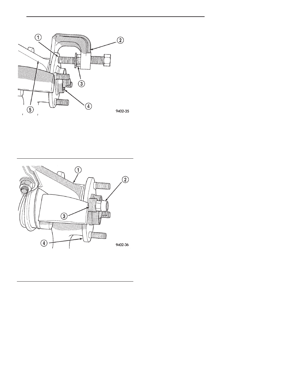
Fig. 60 Removing Wheel Stud From Hub And

Bearing

1 – WHEEL STUD
2 – SPECIAL TOOL C-4150A
3 – LUG NUT
4 – FRONT HUB
5 – STEERING KNUCKLE

Fig. 61 Installing Wheel Stud Into Hub

1 – STEERING KNUCKLE
2 – WHEEL LUG NUT
3 – WASHERS
4 – FRONT HUB

JX

SUSPENSION

2 - 33

REMOVAL AND INSTALLATION (Continued)

NOTE: Before removing the coil spring from the
spring compressor, note the position of the lower
coil spring end to the spring compressor. The coil
spring will need to be in this position on reassem-
bly for proper coil spring-to-shock absorber and
upper mounting bracket orientation.

(7) Release the tension from the coil spring by

backing off the compressor drive fully. Push back the
compressor upper hooks and remove the upper
mounting bracket and upper control arm from the
coil spring.

(8) Note the position of the coil spring in the

spring compressor as listed in the above note before

Fig. 62 Lower Hooks And Clamp

1 – COMPRESSOR
2 – CLAMP
3 – COIL SPRING
4 – LOWER HOOKS

Fig. 63 Upper Hooks Positioned

1 – UPPER HOOKS
2 – UPPER MOUNTING BRACKET
3 – UPPER CONTROL ARM
4 – UPPER BALL JOINT
5 – FRONT HOOK

Fig. 64 Retainer Nut Removal/Installation

1 – SHOCK ABSORBER SOCKET SNAP-ON A136
2 – CROW FOOT

Fig. 65 Washer

1 – SHOCK ABSORBER/UPPER CONTROL ARM MOUNTING

BRACKET

2 – ISOLATOR BUSHING
3 – WASHER

2 - 34

SUSPENSION

JX

DISASSEMBLY AND ASSEMBLY (Continued)

removal. This is necessary for proper alignment of
the shock assembly components when reassembly is
made. Remove the coil spring from the spring com-
pressor.

(9) Remove the shock absorber rod upper isolator

bushing from the upper (shock absorber/upper con-
trol arm) mounting bracket (Fig. 66).

(10) Remove the shock absorber rod lower isolator

bushing and sleeve from the upper (shock absorber/
upper control arm) mounting bracket (Fig. 67).
Remove upper coil spring isolator from mounting
bracket.

NOTE: If removal of the upper control arm is nec-
essary, refer to UPPER CONTROL ARM in the
REMOVAL AND

INSTALLATION

section

of

this

group.

(11) Remove the lower shock rod bushing retainer

washer from the shock absorber rod (Fig. 68).

(12) Remove the dust shield and cup as an assem-

bly from the shock absorber rod by pulling both
straight up and off the shock rod (Fig. 68). The
jounce bumper may come off at the same time.
Remove the jounce bumper and metal collar.

(13) Remove the lower spring isolator (Fig. 68)

from the lower spring seat on the shock absorber.

(14) Inspect the shock assembly components for

the following and replace as necessary:

• Inspect the shock for any condition of rod bind-

ing over the full stroke of the shaft.

Fig. 66 Shock Absorber Rod Upper Isolator Bushing

1 – SHOCK ABSORBER/CONTROL ARM MOUNTING BRACKET
2 – SHOCK ABSORBER ROD UPPER ISOLATOR BUSHING

Fig. 67 Shock Absorber Rod Lower Isolator Bushing

1 – SHOCK ABSORBER/CONTROL ARM MOUNTING BRACKET
2 – UPPER SPRING ISOLATOR
3 – SLEEVE
4 – LOWER ISOLATOR BUSHING

Fig. 68 Shock Assembly Components

1 – SHOCK ABSORBER ROD BUSHING
2 – UPPER CONTROL ARM
3 – RETAINER WASHER
4 – COIL SPRING
5 – SHOCK ABSORBER
6 – LOWER SPRING ISOLATOR
7 – JOUNCE BUMPER
8 – DUST SHIELD
9 – CUP
10 – UPPER SPRING ISOLATOR
11 – UPPER MOUNTING BRACKET

JX

SUSPENSION

2 - 35

DISASSEMBLY AND ASSEMBLY (Continued)

• Check the upper mounting bracket for cracks,

distortion and any sign of damage.

• Inspect the upper mounting bracket-upper con-

trol bushings for deterioration of the rubber.

• Check the upper and lower shock rod isolator

bushings for severe deterioration of the rubber.

• Check the upper and lower spring isolators for

severe deterioration of the rubber.

• Inspect the dust shield for rips and deteriora-

tion.

• Inspect the jounce bumper for cracks and signs

of deterioration.

• Inspect the coil spring for any sign of damage to

the coating.

ASSEMBLY

NOTE: If the coil spring, upper mounting bracket,
rod bushings, upper coil spring isolator, and upper
control arm have been removed from the spring
compressor, proceed with the next step, otherwise,
proceed with step 7.

NOTE: If installation of the upper control arm on
the upper mounting bracket is necessary, refer to
UPPER CONTROL ARM in the REMOVAL AND
INSTALLATION section of this group to reinstall the
upper control arm on the upper mounting bracket
before proceeding.

(1) Install the upper coil spring isolator on the

upper (shock absorber/upper control arm) mounting
bracket (Fig. 67).

CAUTION: The top and bottom shock absorber rod
isolator bushings are unique to the position which
they are installed on the rod. When installing the
bushings on the rod, attention must be paid to their
location so they are installed correctly (Fig. 69).

(2) Install the sleeve into the lower shock absorber

rod isolator bushing (Fig. 67). Install the shock
absorber rod lower isolator bushing and sleeve in the
bottom of the upper (shock absorber/upper control
arm) mounting bracket as shown (Fig. 67). From the
top, install the shock absorber rod upper isolator
bushing into the center of the upper mounting
bracket over the sleeve protruding from the lower
isolator bushing (Fig. 66). The smaller end of each
bushing is to face away from the upper mounting
bracket once installed.

(3) Place the lower end (smaller diameter) of the

coil spring in the spring compressor supported by the
lower hooks, following the manufacturer’s instruc-
tions. Position the coil spring lower end tip at the
position it was at before coil spring removal from the

compressor as noted in step of DISASSEMBLY.
Proper orientation of the spring in the compressor is
necessary for proper alignment of all shock assembly
components.

(4) Install the upper (shock absorber/upper control

arm) mounting bracket on top of the coil spring
matching the coil spring to its isolator on the upper
mounting bracket. Position the upper control arm
ball joint so it lies directly below the front upper
hook as shown (Fig. 63).

(5) Position the upper hooks on top of the upper

mounting bracket as shown (Fig. 63).

(6) Compress the coil spring.
(7) Install the lower spring isolator on the lower

spring seat of the shock absorber (Fig. 68). When
installing the spring isolator, be sure the isolator sets
in the notch made for the lower coil spring end.

(8) Install the jounce bumper on the shock rod

(Fig. 70). Install the jounce bumper with the pointed
end pointing downward.

(9) Install the collar, undercut side facing down, on

the rod of the shock absorber (Fig. 71). Be sure the
collar is positioned squarely on the step of the shock
absorber rod.

(10) Install the dust shield and cup (Fig. 68) onto

the shock rod until the cup contacts the collar just
installed. The dust boot will snap over the jounce
bumper. Install the lower shock rod bushing retainer
washer.

(11) Install the shock through the bottom of the

coil spring until the lower spring seat contacts the
lower end of the coil spring. The lower coil spring end
should set into the notch of the shock absorber lower
seat and isolator. Install the clamp temporarily
securing the shock absorber to the coil spring (Fig.
62).

Fig. 69 Upper And Lower Shock Absorber Rod

Bushing Identification

1 – INSTALL ON SHOCK ABSORBER ROD IN THIS DIRECTION
2 – SHOCK ABSORBER ROD UPPER ISOLATOR BUSHING
3 – INSTALL ON SHOCK ABSORBER ROD IN THIS DIRECTION
4 – SHOCK ABSORBER ROD LOWER ISOLATOR BUSHING

2 - 36

SUSPENSION

JX

DISASSEMBLY AND ASSEMBLY (Continued)


Content   ..  54  55  56  57   ..