Chrysler Stratus Convertible. Manual - part 15


  Index      Chrysler     Chrysler Stratus Convertible - service repair manual 1995-2000 year


Search            


Content   ..  13  14  15  16   ..


Chrysler Stratus Convertible. Manual - part 15


THROTTLE CABLE—2.5L

REMOVAL

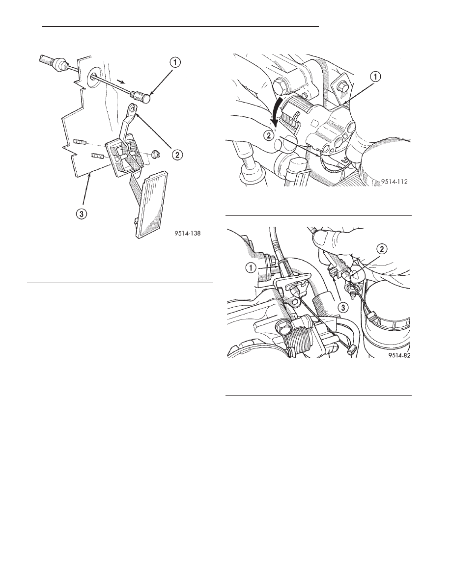
(1) Working from the engine compartment, remove

throttle cable from the throttle body lever (Fig. 33).

(2) Push release tang toward dash panel on throt-

tle cable and slide cable out of bracket (Fig. 34).

(3) From inside the vehicle, reach behind the top

of the pedal shaft and push the retainer toward rear
of vehicle. It may be necessary to squeeze retainer
ears together on dash side of pedal shaft.

(4) Lift cable up through slot in top of pedal shaft.
(5) Remove throttle cable clip attached at grommet

in front of dash panel.

(6) From the engine compartment, pull the throttle

cable and grommet out of the dash panel.

INSTALLATION

(1) From the engine compartment, push the cable

end fitting and grommet into the dash panel.

(2) Install throttle cable clip.

(3) Install cable housing (throttle body end) into

the cable mounting bracket on the engine.

(4) Place cable through slot in top of pedal shaft.
(5) While holding the pedal lever, push retainer clip

forward in vehicle engaging it into the pedal lever.

(6) From the engine compartment, rotate the

throttle lever forward to the wide open position and
install cable clasp.

Fig. 32 Accelerator Pedal and Throttle Cable

1 – CABLE
2 – PEDAL SHAFT
3 – DASH PANEL

Fig. 33 Throttle Cable Attachment to Throttle Body

1 – THROTTLE LEVER
2 – THROTTLE CABLE

Fig. 34 Throttle Cable Attachment

1 – SPEED CONTROL CABLE
2 – THROTTLE CABLE
3 – RELEASE TANG

JX

FUEL SYSTEM

14 - 19

REMOVAL AND INSTALLATION (Continued)

SPECIFICATIONS

TORQUE

DESCRIPTION

TORQUE

Accelerator Pedal to Dash Nuts . . . . . . . . . 12 N·m

(105 in. lbs.)

Fuel Filter Mounting Screw . . 12 N·m (110 in. lbs.)
Fuel Pump Module Locknut . . 74.5 N·m (55 ft. lbs.)
Fuel Tank strap Bolts . . . . . 28.2 N·m (250 in. lbs.)
Fuel Rail Bolts—2.0/2.4L . . . 22.5 N·m (200 in. lbs.)
Fuel Rail Bolts—2.5L . . . . . . . 12 N·m (106 in. lbs.)
Ignition Coil Mounting Bolts . . . 12 N·m (105 in. lbs.)

FUEL TANK CAPACITY

Fig. 35 Cable Routing 2.5L

1 – THROTTLE CABLE

Vehicle

Liters

U. S. Gallons

JX

60

16

Nominal refill capacities are shown. A variation may
be observed from vehicle to vehicle due to
manufacturing tolerance and refill procedure.

14 - 20

FUEL SYSTEM

JX

REMOVAL AND INSTALLATION (Continued)

FUEL INJECTION SYSTEM

TABLE OF CONTENTS

page

page

DESCRIPTION AND OPERATION

INJECTION SYSTEM . . . . . . . . . . . . . . . . . . . . . . 21
PCM REPLACEMENT . . . . . . . . . . . . . . . . . . . . . 22
MODES OF OPERATION . . . . . . . . . . . . . . . . . . . 22
SYSTEM DIAGNOSIS. . . . . . . . . . . . . . . . . . . . . . 24
CCD BUS. . . . . . . . . . . . . . . . . . . . . . . . . . . . . . . 24
POWERTRAIN CONTROL MODULE. . . . . . . . . . . 24
AUTOMATIC SHUTDOWN (ASD) SENSE—

PCM INPUT . . . . . . . . . . . . . . . . . . . . . . . . . . . 25

BATTERY VOLTAGE—PCM INPUT. . . . . . . . . . . . 26
ENGINE COOLANT TEMPERATURE

SENSOR—PCM INPUT . . . . . . . . . . . . . . . . . . . 26

FUEL LEVEL SENSOR—PCM INPUT . . . . . . . . . . 27
HEATED OXYGEN SENSORS—PCM INPUT . . . . 27
IGNITION SENSE—PCM INPUT . . . . . . . . . . . . . . 28
INTAKE AIR TEMPERATURE SENSOR—PCM

INPUT . . . . . . . . . . . . . . . . . . . . . . . . . . . . . . . . 28

MANIFOLD ABSOLUTE PRESSURE (MAP)

SENSOR—PCM INPUT . . . . . . . . . . . . . . . . . . . 28

POWER STEERING PRESSURE SWITCH—

PCM INPUT . . . . . . . . . . . . . . . . . . . . . . . . . . . 30

SENSOR RETURN—PCM INPUT . . . . . . . . . . . . . 30
SCI RECEIVE—PCM INPUT. . . . . . . . . . . . . . . . . 30
THROTTLE POSITION SENSOR—PCM INPUT . . 30
VEHICLE SPEED AND DISTANCE—PCM

INPUT . . . . . . . . . . . . . . . . . . . . . . . . . . . . . . . . 31

AUTOMATIC SHUTDOWN RELAY—PCM

OUTPUT . . . . . . . . . . . . . . . . . . . . . . . . . . . . . . 31

PROPORTIONAL PURGE SOLENOID—PCM

OUTPUT . . . . . . . . . . . . . . . . . . . . . . . . . . . . . . 32

IDLE AIR CONTROL MOTOR—PCM OUTPUT . . . 32
DATA LINK CONNECTOR. . . . . . . . . . . . . . . . . . . 33
MALFUNCTION INDICATOR (CHECK ENGINE)

LAMP—PCM OUTPUT . . . . . . . . . . . . . . . . . . . 33

RADIATOR FAN RELAYS—PCM OUTPUT . . . . . . 34
TACHOMETER—PCM OUTPUT . . . . . . . . . . . . . . 34
5 VOLT SUPPLY—PCM OUTPUT . . . . . . . . . . . . . 34
8-VOLT SUPPLY—PCM OUTPUT . . . . . . . . . . . . . 34
THROTTLE BODY . . . . . . . . . . . . . . . . . . . . . . . . 34

REMOVAL AND INSTALLATION

THROTTLE BODY—2.5L ENGINE . . . . . . . . . . . . 35
THROTTLE POSITION SENSOR (TPS)—2.5L. . . . 35
IDLE AIR CONTROL MOTOR—2.0/2.4/2.5L . . . . . 36
INTAKE AIR TEMPERATURE SENSOR—2.5L. . . . 37
MANIFOLD ABSOLUTE PRESSURE (MAP)

SENSOR . . . . . . . . . . . . . . . . . . . . . . . . . . . . . . 37

POWERTRAIN CONTROL MODULE. . . . . . . . . . . 37
OXYGEN SENSOR 1/1 UPSTREAM—2.5L . . . . . . 38
OXYGEN SENSOR 1/2 DOWNSTREAM . . . . . . . . 38
AIR INLET RESONATOR . . . . . . . . . . . . . . . . . . . 39
AIR CLEANER . . . . . . . . . . . . . . . . . . . . . . . . . . . 40
FILTER ELEMENT REPLACEMENT . . . . . . . . . . . 40
ENGINE COOLANT TEMPERATURE SENSOR . . . 40

SPECIFICATIONS

VEHICLE EMISSION CONTROL

INFORMATION LABEL . . . . . . . . . . . . . . . . . . . 41

TORQUE . . . . . . . . . . . . . . . . . . . . . . . . . . . . . . . 41

SPECIAL TOOLS

FUEL . . . . . . . . . . . . . . . . . . . . . . . . . . . . . . . . . . 42

DESCRIPTION AND OPERATION

INJECTION SYSTEM

OPERATION

All engines used in this section have a sequential

Multi-Port Electronic Fuel Injection system. The MPI
system is computer regulated and provides precise
air/fuel ratios for all driving conditions. The Power-
train Control Module (PCM) operates the fuel injec-
tion system.

The PCM regulates:
• Ignition timing

• Air/fuel ratio

• Emission control devices

• Cooling fan

• Charging system

• Idle speed

• Vehicle speed control
Various sensors provide the inputs necessary for

the PCM to correctly operate these systems. In addi-
tion to the sensors, various switches also provide
inputs to the PCM.

The PCM can adapt its programming to meet

changing operating conditions.

Fuel is injected into the intake port above the

intake valve in precise metered amounts through
electrically operated injectors. The PCM fires the
injectors in a specific sequence. Under most operat-
ing conditions, the PCM maintains an air fuel ratio
of 14.7 parts air to 1 part fuel by constantly adjust-
ing injector pulse width. Injector pulse width is the
length of time the injector is open.

The PCM adjusts injector pulse width by opening

and closing the ground path to the injector. Engine

JX

FUEL SYSTEM

14 - 21

RPM (speed) and manifold absolute pressure (air
density) are the primary inputs that determine injec-
tor pulse width.

PCM REPLACEMENT

DESCRIPTION

USE THE DRB SCAN TOOL TO REPROGRAM

THE NEW PCM WITH THE VEHICLES ORIGI-
NAL IDENTIFICATION NUMBER (VIN) AND
THE VEHICLES ORIGINAL MILEAGE. IF THIS
STEP IS NOT DONE A DIAGNOSTIC TROUBLE
CODE (DTC) MAY BE SET.

MODES OF OPERATION

OPERATION

As input signals to the PCM change, the PCM

adjusts its response to output devices. For example,
the PCM must calculate a different injector pulse
width and ignition timing for idle than it does for
Wide Open Throttle (WOT). There are several differ-
ent modes of operation that determine how the PCM
responds to the various input signals.

There are two different areas of operation, OPEN

LOOP and CLOSED LOOP.

During OPEN LOOP modes the PCM receives

input signals and responds according to preset PCM
programming. Inputs from the upstream and down-
stream heated oxygen sensors are not monitored dur-
ing OPEN LOOP modes, except for heated oxygen
sensor diagnostics (they are checked for shorted con-
ditions at all times).

During CLOSED LOOP modes the PCM monitors

the inputs from the upstream and downstream
heated oxygen sensors. The upstream heated oxygen
sensor input tells the PCM if the calculated injector
pulse width resulted in the ideal air-fuel ratio of 14.7
to one. By monitoring the exhaust oxygen content
through the upstream heated oxygen sensor, the
PCM can fine tune injector pulse width. Fine tuning
injector pulse width allows the PCM to achieve opti-
mum fuel economy combined with low emissions.

For the PCM to enter CLOSED LOOP operation,

the following must occur:

(1) Engine coolant temperature must be over 35°F.
• If the coolant is over 35° the PCM will wait 44

seconds.

• If the coolant is over 50°F the PCM will wait 38

seconds.

• If the coolant is over 167°F the PCM will wait

11 seconds.

(2) For other temperatures the PCM will interpo-

late the correct waiting time.

(3) O2 sensor must read either greater than 0.745

volts or less than 0.1 volt.

(4) The multi-port fuel injection systems has the

following modes of operation:

• Ignition switch ON (Zero RPM)

• Engine start-up

• Engine warm-up

• Cruise

• Idle

• Acceleration

• Deceleration

• Wide Open Throttle

• Ignition switch OFF
(5) The engine start-up (crank), engine warm-up,

deceleration with fuel shutoff and wide open throttle
modes are OPEN LOOP modes. Under most operat-
ing conditions, the acceleration, deceleration (with
A/C on), idle and cruise modes, with the engine at
operating temperature 
are CLOSED LOOP modes.

IGNITION SWITCH ON (ZERO RPM) MODE

When the ignition switch activates the fuel injec-

tion system, the following actions occur:

• The PCM monitors the engine coolant tempera-

ture sensor and throttle position sensor input. The
PCM determines basic fuel injector pulse width from
this input.

• The PCM determines atmospheric air pressure

from the MAP sensor input to modify injector pulse
width.

When the key is in the ON position and the engine

is not running (zero rpm), the Auto Shutdown (ASD)
and fuel pump relays de-energize after approximately
1 second. Therefore, battery voltage is not supplied to
the fuel pump, ignition coil, fuel injectors and heated
oxygen sensors.

ENGINE START-UP MODE

This is an OPEN LOOP mode. If the vehicle is in

park or neutral (automatic transaxles) or the clutch
pedal is depressed (manual transaxles) the ignition
switch energizes the starter relay. The following
actions occur when the starter motor is engaged.

• If the PCM receives the camshaft position sensor

and crankshaft position sensor signals, it energizes
the Auto Shutdown (ASD) relay and fuel pump relay.
If the PCM does not receive both signals within
approximately one second, it will not energize the
ASD relay and fuel pump relay. The ASD and fuel
pump relays supply battery voltage to the fuel pump,
fuel injectors, ignition coil and heated oxygen sen-
sors.

• The PCM energizes the injectors (on the 69°

degree falling edge) for a calculated pulse width until
it determines crankshaft position from the camshaft
position sensor and crankshaft position sensor sig-
nals. The PCM determines crankshaft position within
1 engine revolution.

14 - 22

FUEL SYSTEM

JX

DESCRIPTION AND OPERATION (Continued)


Content   ..  13  14  15  16   ..