Chrysler New Yorker. Manual - part 301
 

  Index      Chrysler     Chrysler New Yorker - service repair manual 1997-1999 year


Search            


Content   ..  299  300  301  302   ..


Chrysler New Yorker. Manual - part 301


special tools described in this procedure must be
used to obtain correct results.

CAUTION: Failure to adjust pinion depth correctly
could cause gear noise or transaxle failure.

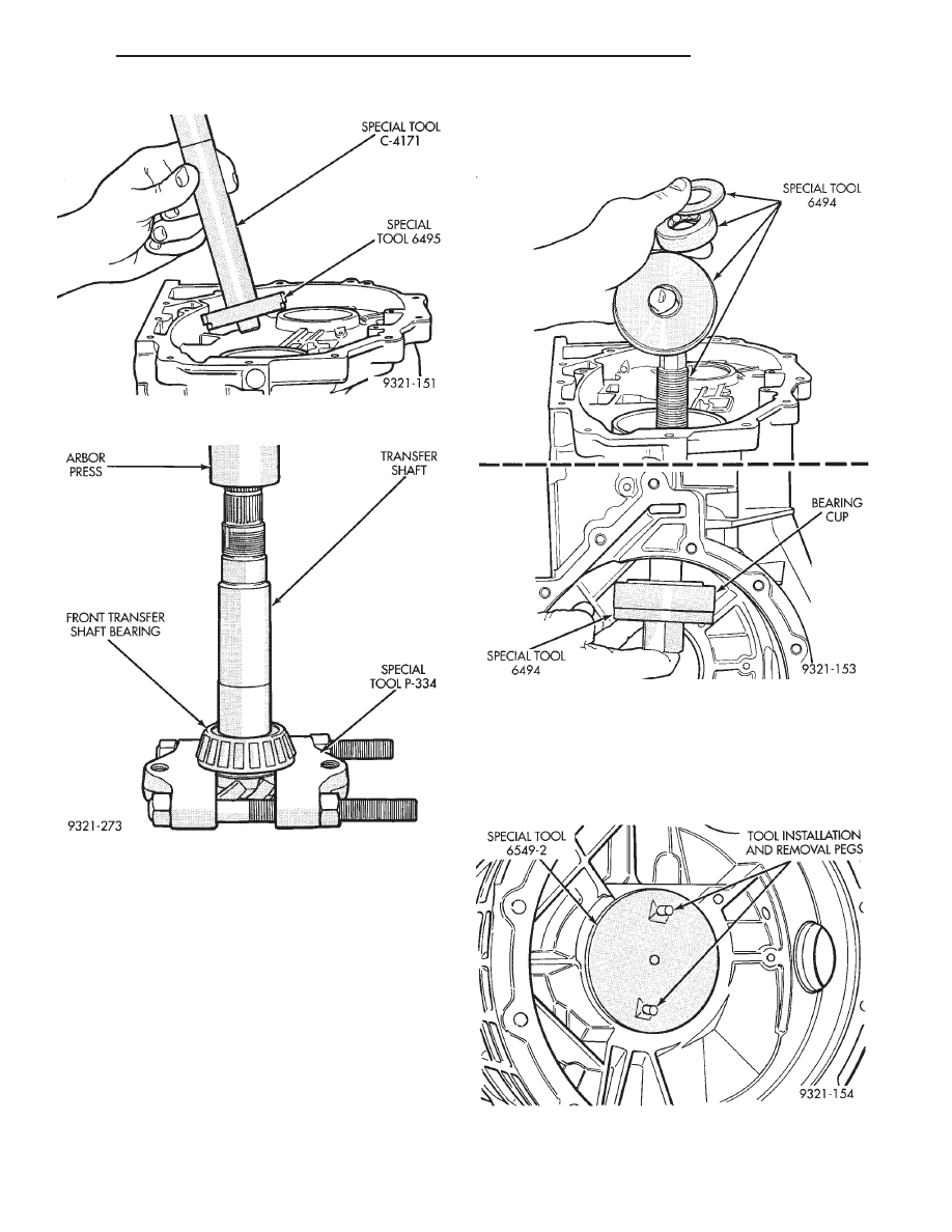
(1) Install front transfer shaft bearing cup (Fig.

300). The transfer shaft bearing cup must be
installed before making pinion depth measurement.
Use special tool 6494 to install bearing cup. There
are no shims located behind this bearing cup.

CAUTION: The bearing cup is seated in the case
correctly if there is no clearance between the bottom

of the bearing cup and case. If a 0.001

(

or 0.002

(

feeler gauge does not fit, the bearing cup is com-
pletely seated into transaxle case.

(2) Install centering block (special tool 6549-2) into

the transaxle case (Fig. 301). Screw centering block
into inner adjuster hole of case until it bottoms. The
pegs on the special tool are only used for installation.
Orientation with in the case is not required.

Fig. 298 Front Transfer Shaft Cup Removal

Fig. 299 Remove Front Transfer Shaft Bearing And

Pinion Depth Shim

Fig. 300 Install Front Transfer Shaft Cup

Fig. 301 Installing Centering Block

300M

TRANSAXLE

21 - 77

DISASSEMBLY AND ASSEMBLY (Continued)

(3) Install new front bearing (actual bearing to be

used during reassembly) onto gauge disc (special tool
6549-3) (Fig. 302).

(4) Install gauge disc and bearing into case using

gauge disc rod Tool 6549-4 (Fig. 303).

(5) Install centering disc (special tool 6494-2) onto

gauge disc rod (Fig. 304).

(6) Install centering nut Tool 6549-5 as shown in

(Fig. 305).

(7) Hand tighten centering nut until all play in the

tool has been removed.

(8) Install dial indicator into locating block Tool

6549-1. Then screw extension rod onto dial indicator.

NOTE: The dial indicator used to make this mea-
surement must have a face that shows 0-50-0 (Spe-
cial Tool C-3339) readings (Fig. 307). All steps from
this point forward will reflect this assumption. This
will give you proper shim thickness.

(9) Before making a pinion depth measurement

the dial indicator must be zeroed. This is done by
placing the dial indicator in the zeroing fixture (spe-
cial tool 6549-6). Then place the zeroing fixture on a
flat surface. Adjust the dial face so the pointer on the
dial indicator lines up with the zero (Fig. 308).

Fig. 302 Gauge Disc and Bearing

Fig. 303 Installing Gauge Disc with Front Transfer

Shaft Bearing

Fig. 304 Disc Installation

Fig. 305 Installing Centering Nut

Fig. 306 Dial indicator, Locating Block and

Extension Rod

21 - 78

TRANSAXLE

300M

DISASSEMBLY AND ASSEMBLY (Continued)

(10) Compress the dial indicator slightly and

insert dial indicator pin into centering block (Fig.
309).

(11) Pivot dial indicator back and forth (Fig. 310)

on centering pin to obtain the shortest distance mea-
surement. This will be the lowest number read-
ing on dial indicator. 
Record the number obtained.
Now rotate the gauge disc clockwise 1/3 of a turn and

recheck readings. Record number obtained. Rotate
the gauge disc another 1/3 of a turn clockwise and
take another reading. Average the three readings.
Record this pinion depth measurement. If the read-
ings differ by more than two thousandths recheck
guage disc installation, it may have been installed
slightly cocked.

(12) To determine the required shim thickness, the

pinion depth measurement must be adjusted. The
pinion shim adjustment number is the first of seven
digits ink stamped on the shank of the transfer shaft
(Fig. 311). Using the adjustment factor chart, convert
the adjustment number to the corresponding adjust-
ment factor. Utilizing the pinion depth measurement
obtained in Step 12, add or subtract the adjustment
factor to calculate the requred shim thickness. Refer
to pinion head shim chart for shim selections. This is
the shim that will be installed between the transfer
shaft pinion head and the front transfer shaft bear-
ing. Refer to the following examples for further
explanation:

(13) Example 1 in (MM):
• Measured pinion shim depth: 0.789mm

• Adjustment number on transfer shaft: +2

• Adjustment factor (mm): -0.051mm

• Shim size needed: 0.789-0.051=0.738mm
(14) Example 2 in (IN):
• Measured pinion shim depth: 0.032in

• Adjustment number on transfer shaft: -1

• Adjustment factor (in): +0.001

• Shim size needed: 0.032+0.001=0.033in
(15) Remove dial indicator, gauge disc and center-

ing block from transaxle.

(16) Install shim selected in Step 13 of this proce-

dure onto the transfer shaft (Fig. 311).

(17) Press front transfer shaft bearing onto trans-

fer shaft (special tool 6052). The shim must be in
place before pressing on bearing (Fig. 312).

Fig. 307 0-50-0 Dial Indicator

Fig. 308 Zero Dial Indicator

Fig. 309 Mounting Dial Indicator to Centering Block

Fig. 310 Pivot Dial Indicator

300M

TRANSAXLE

21 - 79

DISASSEMBLY AND ASSEMBLY (Continued)

(18) At this point the pinion depth has been deter-

mined and the shim has been installed onto the
transfer shaft. Before the pinion is installed into the
transaxle case, bearing preload must be determined
for the differential bearings. The following steps
must be performed before the pinion is installed.

(19) The following steps will determine how many

foot pounds are required on the outer differential
adjuster to obtain the correct turning torque.

CAUTION: Failure to set differential bearing preload
correctly may cause bearing failure, gear noise
and/or axle shaft seal failure.

(20) Remove outer adjuster with special tool 6503

(Fig. 313).

(21) Remove old stub shaft seals. Press inner

adjuster seal out with special tool 6502B. Press outer
adjuster seal out with special tool 6558.

(22) Install new stub shaft seals in both adjusters

using special tool 6558 (Fig. 314).

NOTE: To remove inner and outer adjuster races,
use Tool 6062–A. To install inner and outer adjuster
races, use Tool 6522 and Tool C-4171.

ADJUSTMENT FACTOR CHART

PINION HEAD SHIM CHART

Fig. 311 Shim Installation

Fig. 312 Bearing Installation

21 - 80

TRANSAXLE

300M

DISASSEMBLY AND ASSEMBLY (Continued)


Content   ..  299  300  301  302   ..