Chery QQ6 (Body Accessories and Dimensions). Service Manual - part 4


  Index      Chery     Chery QQ6 (Body Accessories and Dimensions). Service Manual


Search            copyright infringement  


Content      ..     2      3      4      5     ..


Chery QQ6 (Body Accessories and Dimensions). Service Manual - part 4


49 

2. Preparation 

No.10 sleeve and No.7  open end  wrench, cross 

head screwdriver and flat head screwdriver. 

3. Precautions 

3.1  Please  wear  necessary  labor  protection 

supplies to avoid accidents. 

3.2  To  prevent  scratch  the  bumper  surface 

paint. 

3.3.  In  case  of  disassembly/reassembly  in  the 

low temperature environment, the force applied 

can’t  be  big  so  as  to  avoid  the  breakage  of  the 

bumper.  Disconnect  the  control  switch  of 

corresponding  lamps,  and  remove  the  wire 

connected to the battery. 

3.4. When the headlamp is being removed, pay 

more  attention  to  its  clips  on  the  bumper.  The 

big force may damage the clips.   

3.5  Pay  attention  to  not  scratch  the  headlamp 

surface when disassemble and place. 

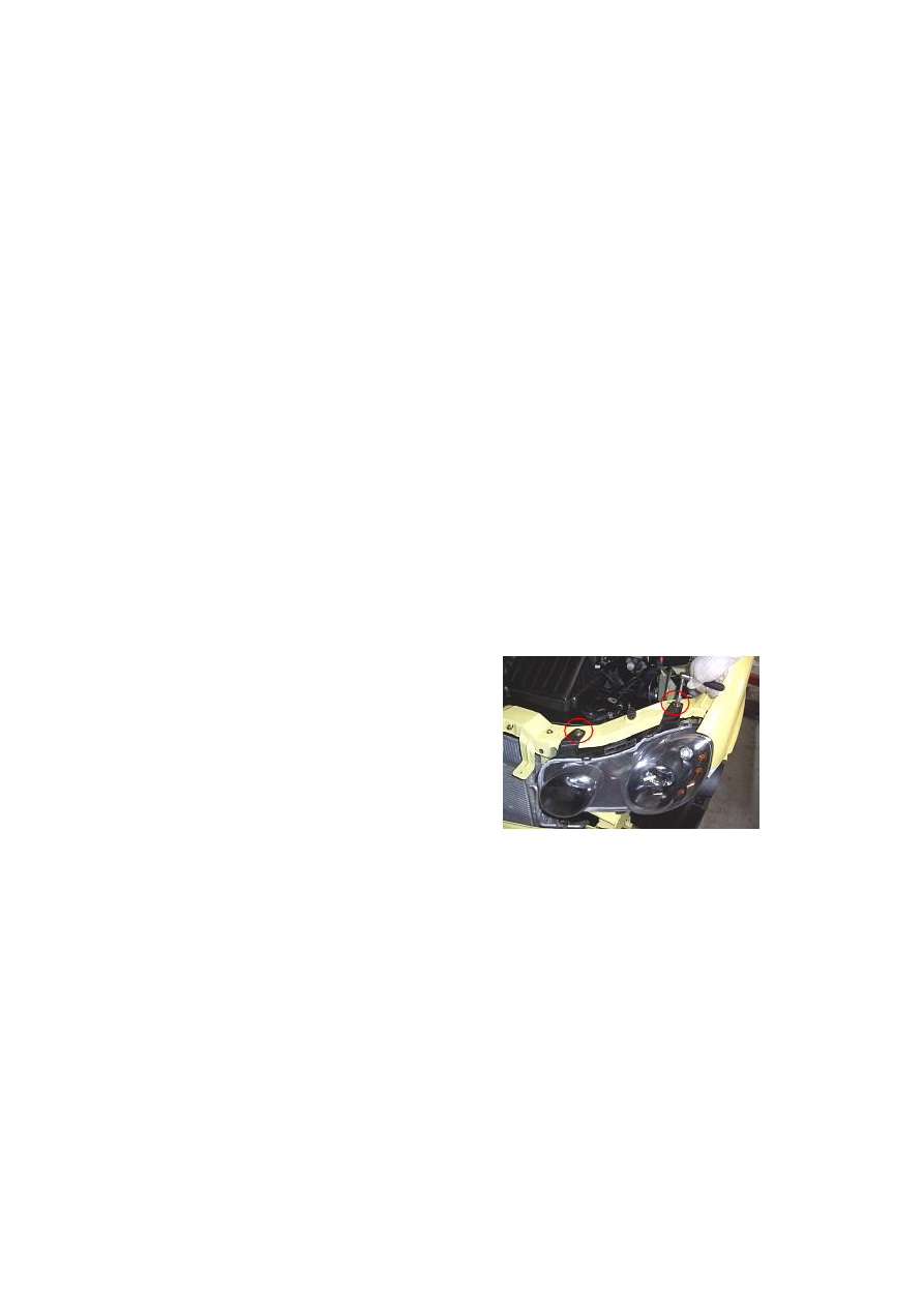
4. Removal Step of Headlamp 

4.1.  Disassemble  front  bumper  assy  first.  (See 

disassembly/assembly of bumper) 

4.2.  Loosen  headlamp  two  fixing  bolts  on 

engine hood cross beam with No.10 sleeve. 

Torque: 3.5±0.5N·m   


-------------------------------------------------------------------------------------------------------------------------------------------------------------

50 


4.3.  Remove  the  fixing  bolts  under  the 

headlamp with a cross screwdriver. 

Torque: 1.8±0.2N·m 


4.4.  Pull  out  the  plug  from  the  headlamp,  and 

then take off the headlamp assy.   


4.5. Open the lamp holder clips by hand.   


4.6. Pull out two harness connectors by hand.   


4.7.  Remove  two  fix  screws  with  a  cross 

screwdriver.   


-------------------------------------------------------------------------------------------------------------------------------------------------------------

51 


4.8. Hold the bulb seat by hand, and take off the 

bulb from the headlamp.   


CAUTION:  In  case  that  the  bulb  is  replaced, 

DO  NOT  contact  the  bulb  by  hand,  otherwise 

the  fingerprint  remained  on  the  bulb  is  heated 

and  volatilzes  after  the  lamp  lights,  and  then 

deposits  on  the  mirror  surface,  which  may 

result that the reflector darkens.   


4.9. Screw off headlamp high beam seat cover. 


4.10. Pull out two harness connectors by hand.   


4.11.  Remove  two  fix  screws  with  a  cross 

screwdriver.   


-------------------------------------------------------------------------------------------------------------------------------------------------------------

52 


4.12.  Hold  the  bulb  seat  by  hand,  and  take  off 

the bulb from the headlamp. 


CAUTION:  In  case  that  the  bulb  is  replaced, 

DO  NOT  contact  the  bulb  by  hand,  otherwise 

the  fingerprint  remained  on  the  bulb  is  heated 

and  volatilzes  after  the  lamp  lights,  and  then 

deposits  on  the  mirror  surface,  which  may 

result that the reflector darkens. 


5. Removal of Fog Lamp 

5.1.  Remove  the  bumper  assy.  Refer  to 

Disassembly of Bumper. 

5.2. Pull out the plug of fog lamp.   


5.3.  Unscrew  three  fixing  nuts  from  the  fog 

lamp with a cross screwdriver.   


5.4 Take off the fog lamp assy.   


-------------------------------------------------------------------------------------------------------------------------------------------------------------

53 


6.  Installation  and  Adjustment  of 
Headlamp 

6.1. headlamp Installation Step 

The  installing  steps  of  headlamp  are 

reverse to those for removal. 

6.2. Introduction to headlamp function 

6.2.1. Front view 

See right figure: 

Low beam light 

Position light 

High beam 

Turn light 


6.2.2. Back view 

See right figure: 

Low 

beam 

light 

holder 

Headlamp’s plug 

High 

beam 

light 

holder 

High 

beam 

up/down 

adjusting nut 

High beam left/right adjusting nut 

Low beam up/down adjusting nut 

Low beam left/right adjusting nut 


6.3. Adjustment of headlamp light 

Headlamp  uses  half  closed  light  combination  type.  So  it  is  easy  to  be  maintained;  it  is  halogen 

light with less mechanism and high luminous intensity, which will prolong bulb life. 

The  correctness  of  headlamp  adjustment  will  influence  the  driving  safety.  So  it  needs  special 

device to adjust the beam. Pay attention to law regulations and verify the following items before 

adjustment: 

a. 

Tire pressure should be conformity with standard; 

b. 

Car  is  unload  (except  for  spare  tire  and  equipped  tools,  and  include  driver  weigh  for 

sedan); 

c. 

Park the car on horizontal road or workplace; 

d. 

The lens surface of headlamp should be clean; 

e. 

Check the power supplies if is working correctly, and the bulb installed correctly. 

-------------------------------------------------------------------------------------------------------------------------------------------------------------

54 


Adjust  the  governing  mechanism  equipped  on 

the  lamps  to  implement  the  adjustment 

rightward  and  leftward,  upward  and  downward 

of  the  lamp  beam,  according  to  the  required 

values  in  national  standards.  The  coarse  and 

fine  adjustment  upward  and  downward  is 

integrated  into  one  entity,  which  is  located  at 

the  upper  edge  of  housing  while  the  rightward 

and  leftward  adjustment  mechanism  is  located 

at the central lower edge of the housing.   

It needs take off headlamp cover to adjust right 

headlamp.  The  left  headlamp  and  right 

headlamp  adjusting  mechanisms  are  arranged 

symmetrically,  with  the  same  adjustment 

method is the same.   

6.3.3.  The  beam  of  headlamp  can  be  adjusted 

with the light adjusting nut or electric adjusting 

pushbutton (if equipped).   

6.3.3.1.  Insert  a  cross  screwdriver  into  the 

corresponding  adjustment  hole  to  adjust  the 

beam. 

6.3.3.2.  Height  of  CHERY  S21’s  standard 

headlamp reference center:   

Low beam: 717 mm; High beam: 755 mm. 

6.3.3.3.  The  headlamp  light  beam  shall  be 

adjusted  according  to  the  data  specified  in  the 

national stardards:   

When  checking  the  dip  beam  (i.e.  low  beam) 

headlamp  position,  project  the  headlamp  on  a 

screen 10 m away, the dark and bright changing 

line  angle  or  central  height  shall  be  0.7H  –  0.9 

H  (H  is  the  height  of  the  headlamp  reference 

center,  the  same  below)  for  passenger  cars,  it 

shall be    0.6H – 0.8 H for other motor vehicles 

(excluding transportation tractor combinations). 

The  horizontal  deviation  to  the  left  of  the 

dipped headlamp for motor vehicles (except the 

vehicle  with  only  one  headlamp)  shall  not 

exceed 10  mm and the right  deviation shall  not 

exceed 350 mm.   

(From national standard) 

6.3.3.5. Please input the standard  data obtained 

into  the  headlamp  beam  regulator  for  the 

convenience to use in the furture. 


-------------------------------------------------------------------------------------------------------------------------------------------------------------

55 


7. Tail Lamp Removal Step 

7.1.  Remove  the  fix  screws  from  the  tail  lamp 

with a cross screwdriver.   


7.2.  Open  the  trunk,  and  lift  up  the  carpet  of 

trunk.   


7.3. Remove the upper seat fixing nuts from tail 

lamp with a fix wrench.   


7.4. Remove the lower seat fixing nuts from tail 

lamp with a fix wrench. 


7.5.  Pull  out  the  tail  lamp  harness  connector, 

and the take off the tail lamp assy.   


-------------------------------------------------------------------------------------------------------------------------------------------------------------

56 

Chapter 6    Disassembly/Reassembly of Ceiling 

1. Preparation 

Tools:  socket  wrench,  cross  screwdriver,  flat 

head screwdriver 

2. Precautions 

2.1.  During  the  disassembly/reassembly,  pay 

more attention to the application of appropriate 

force, without crude operation.   


2.2.  During  the  disassembly/reassembly  of 

interior  ornaments,  especially  pay  more 

attention to the protection of surface ornaments 

so as to avoid the damage of the ornaments. 

3.  Disassembly/Reassembly 

of 

Sun Visor 

3.1. Removal Step 

3.1.1.  Loosen  two  fixing  screws  on  left  front 

sun visor with a cross head screwdriver 

Torque: 3±1Nm 


3.1.2. Take off the front left sun visor.   


3.2. Installation Step 

The  installing  steps  are  reverse  to  those  for 

removal. 


3.3. Refer to Disassembly/Reassembly  of Front 

Left  Sun  Visor  for  the  disassembly/reassembly 

of front right sun visor.   


-------------------------------------------------------------------------------------------------------------------------------------------------------------

57 


4.  Disassembly/Reassembly 

of 

Roof Hand-Hold 

4.1. Removal Step 

4.1.1.  Remove  the  right/left  fix  screws  with  a 

cross screwdriver.   

Torque: 9±3Nm 


4.1.2. Take off the hand-hold.   

4.2. Installation Step 

The  installing  steps  are  reverse  to  those  for 

removal. 


4.3  Refer  to  Disassembly/Reassembly  of  Front 

Right Hand-Hold for other hand-holds. 


5.  Disassembly/Reassembly 

of 

Front Ceiling Lamp 

5.1. Removal Step 

5.1.1. Remove the front ceiling lamp cover with 

a flat head screwdriver. 

Note: do not scratch part surface. 


5.1.2. Loosen the front ceiling lamp fixing bolt. 

Torque: 1.5±0.5Nm 


-------------------------------------------------------------------------------------------------------------------------------------------------------------

58 


5.1.3.  Pull  out  the  harness  connector,  and  then 

take off the front ceiling lamp assy.   


5.2. Installation Step 

The  installing  steps  are  reverse  to  those  for 

removal. 

6.  Disassembly/Reassembly  of  A 

Pillar Trim 

6.1. Removal Step 

6.1.1. Prize A pillar protective board with a flat 

head screwdriver. 


6.1.2. Take off the A pillar trim.   

6.2. Installation Step 

The  installing  steps  are  reverse  to  those  for 

removal. 

7.  Disassembly/Reassembly  of  B 

Pillar Trim 

7.1. Removal Step 

7.1.1  Remove  B  pillar  lower  protective  board 

(refer to Disassembly/Assembly of Seat Belt) 


-------------------------------------------------------------------------------------------------------------------------------------------------------------

59 


7.1.2.  Remove  the  B  pillar  upper  trim  with  a 

flat head screwdriver.   

Note:  protect  the  trim  part  surface  from 

scratching. 


7.2. Installation Step 

The  installing  steps  are  reverse  to  those  for 

removal. 

8.  Disassembly/Reassembly  of  C 

Pillar Trim 

8.1. Removal Step 

8.1.1.  Refer  to  Disassembly/Reassembly  of 

Rear Passenger Seat and Seat Belt.   


8.1.2.  Remove  the  C  pillar  upper  trim  with  a 

flat head screwdriver.   


8.1.3.  Remove  the  C  pillar  lower  trim  with  a 

flat head screwdriver.   


8.2. Installation Step 

The  installing  steps  are  reverse  to  those  for 

removal. 

9.  Disassembly/Reassembly 

of 

Ceiling 

9.1. Removal Step 

9.1.1  Remove  the  left  and  right  sun 

visors.(Refer  to  Disassembly/Reassembly  of 

Sun Visor) 

9.1.2. Remove the  front ceiling lamp. (Refer to 

Disassembly/Reassembly  of  Front  Ceiling 

Lamp) 

9.1.3  Remove  all  the  roof  hand-hold.(Refer  to 

Disassembly/Reassembly of Roof Hand-Hold) 


-------------------------------------------------------------------------------------------------------------------------------------------------------------

60 


9.1.4.  Remove  the  A/B/C  pillar  trim.  (Refer  to 

Disassembly/Reassembly  of  A/B/C  Pillart 

Trim) 

9.1.5.  Remove  the  ceiling  clips  (5  pcs  in  total) 

with a flat head screwdriver. 


9.1.6.  Remove  the  wheatherproof  rubber  strip 

of four door opening by hand. 


9.1.7.  Open  the  trunk,  and  then  remove  the 

ceiling.  It  is  convenient  to  take  off  the  ceiling 

from  the  trunk  and  not  easy  to  damage  the 

ceiling.   


9.2. Installation Step 

The  installing  steps  are  reverse  to  those  for 

removal. 


-------------------------------------------------------------------------------------------------------------------------------------------------------------

61 

Chapter 7  Disassembly/Reassembly of Instrument Panel 

I. Removal of Instrument Panel Accessories 

1. Preparation 

Tool: socket spanner, cross head screwdriver, flat head screwdriver 

Note: disconnect accumulator cathode before disassemble electrical parts 

2.  Disassembly/Reassembly  of  Central  Console  Panel,  Audio  Unit,  Emergency 
Switch, A/C Control Switch, Ashtray 

2.1. Removal Step 

2.1.1.  Remove  the  central  console  panel  by 

hand.   


2.1.2. Remove four fix screws used to joint the 

audio  unit  and  instrument  panel  body  with  a 

cross screwdriver.   

Torque: 9±3 Nm 


2.1.3.  Remove  two  fix  screws  applied  to  joint 

the  emergency  switch  and  instrument  panel 

body with a cross screwdriver.   

Torque: 1.5±0.5Nm 


2.1.4.  take  off  the  emergency  switch  and  pull 

out the wire harness.   


2.1.5.  take  off  the  audio  and  pull  out  the  wire 

harness.   


-------------------------------------------------------------------------------------------------------------------------------------------------------------

62 


2.1.6. Remove four fix screws used to joint the 

A/C  control  switch  and  instrument  panel  body 

with a cross screwdriver.   

Torque: 3.5±0.5 Nm 


2.1.7.  Remove  the  fix  screws  (at  the  bottom  of 

ashtray) from the console, take off the cigarette 

lighter connecting wire, and remove the console 

assy.   


2.1.8. Remove the A/C control switch cable and 

harness,  and  then  take  off  the  A/C  control 

switch.   

2.2. Installation Step 

The  installing  steps  are  reverse  to  those  for 

removal. 


3.  Disassembly/Reassembly  of  Front 
Ashtray 

3.1. Removal Step 

3.1.1. Draw out the front ashtray.   


Bolts  under 
the astray 

-------------------------------------------------------------------------------------------------------------------------------------------------------------

63 


3.1.2.  Remove  one  fix  screw  from  the  bottom 

of  front  ashtray  guide  run  with  a  cross 

screwdriver. 

Torque: 10±1 Nm 


3.1.3. Remove two fix screws from the front of 

front  ashtray  guide  run  with  a  cross 

screwdriver. 

Torque: 3±1 Nm 


3.1.4. Take off the front ashtray guide run.   

3.2. Installation Step 

The  installing  steps  are  reverse  to  those  for 

removal. 

4.  Disassembly/Reassembly  of  Glove 
Case 

4.1. Removal Step 

4.1.1.  Unclench  the  long  clip  core  at  the  right 

lower part of glove case with a screwdriver, and 

take off the clips.   

4.1.2. Swing and take off the glove case.   

4.2. Installation Step 

The  installing  steps  are  reverse  to  those  for 

removal. 

5. 

combination 


instrument 

Disassembly/Reassembly of   

5.1. Removal Step 

5.1.1.  Remove  the  central  console  panel,  and 

then  remove  the  combination  instrument 

ornament frame. 


Bolts  under 
the astray 


-------------------------------------------------------------------------------------------------------------------------------------------------------------

64 


5.1.2.  Remove  four  fix  screws  from  the 

combination 

instrument 

with 

cross 

screwdriver. 

Torque: 2±0.3Nm 


5.1.3. Disconnec to the combination instrument 

harness  connector,  and  then  take  off  the 

combination instrument.   


5.2. Installation Step 

The  installing  steps  are  reverse  to  those  for 

removal. 


6. 

Disassembly/Reassembly 

of 

Combination  Switch,  Wiper  Switch, 
Ignition Switch, Heliax Cable   

Please  refer  to  Disassembly/Reassembly  of 

Steering  Column  in  the  Service  Manual  of 

Chassis.   


-------------------------------------------------------------------------------------------------------------------------------------------------------------


Content      ..     2      3      4      5     ..