Chery QQ6 (Body Accessories and Dimensions). Service Manual - part 3
 

  Index      Chery     Chery QQ6 (Body Accessories and Dimensions). Service Manual


Search            copyright infringement  


Content      ..     1      2      3      4      ..


Chery QQ6 (Body Accessories and Dimensions). Service Manual - part 3


33 

5. Installation and Adjustment Step 

5.1. The installing steps are reverse to those for 

removal. 

5.2. Adjustment of door 

5.2.1.  After  the  installation  of  door,  check  the 

horizontial  and  vertical  clearances  and  the 

closing  force  of  door.  If  the  clearance  is 

incorrect  and  the  closing  force  is  big,  timely 

adjust  the  clearnace  and  force.  See  Body 

Dimension  for  the  adjustment  of  door 

clearance. 

5.2.2.  The  door  clearance  is  adjusted  by 

regulating the fixing bolts of hinge at the body.   


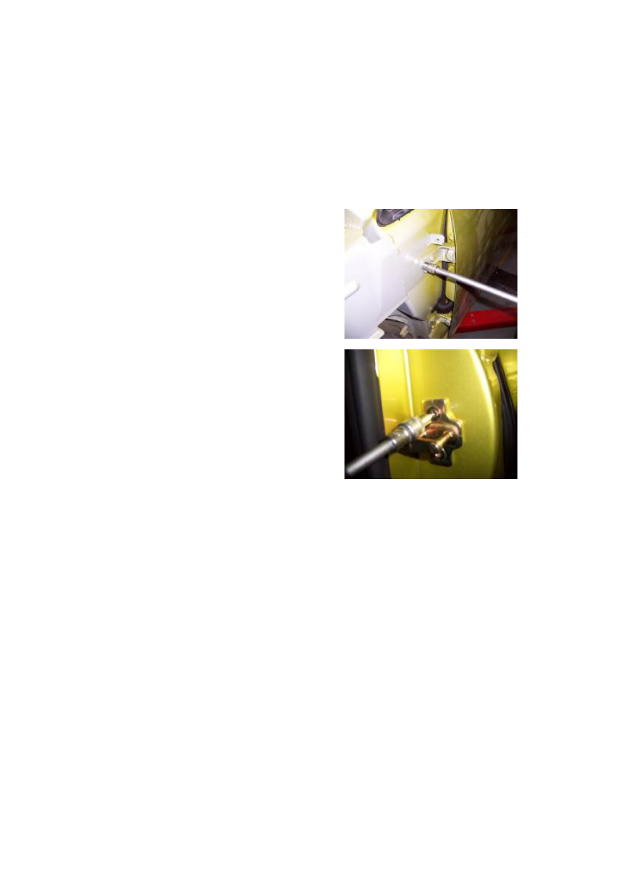
5.2.3. The closing  force  of  door can be slightly 

adjusted by regulating the position of front door 

lock column.   

Torque: 9±1Nm. 


5.3. Adjustment of door glass regulator system. 

5.3.1. Check the window regulator system after 

this  system  is  assembled.  The  duration  of 

window glass lifting from the lowest position to 

the highest position shall be approximate 7 s.   

If  the  time  is  too  long,  check  the  regulator  in 

time. 

5.3.2 Check window regulator motor. 

5.3.3.  Check  whether  there  is  oil  or  dust  in  the 

glass  run  channel  which  may  result  that  the 

resistance is overhigh when the window glass is 

rising. 

CAUTION:  DO  NOT  apply  any  lubricating 

grease on the glass run channel or glass so as to 

avoid the adhesion of dust. 

5.3.4.  Check  whether  the  installation  of  glass 

guide  is  deviated  from  its  proper  position, 

which  may  result  that  the  glass  is  clamped  due 

to  the  nonuniform  arc  scale  when  the  glass  is 

rising.  The  position  of  glass  guide  can  be 

adjusted by the guide fixing bolts. 


-------------------------------------------------------------------------------------------------------------------------------------------------------------

34 

II.  Disassembly/Reassembly  and 

Maintenance of Rear Door 

1. Preparation 

Flat  head  screwdriver,  cross  head  screwdriver, 

No.7, 10, 13 sleeves and pliers. 

2. Precautions 

2.1  Please  wear  necessary  labor  protection 

supplies to avoid accidents. 

2.2 Power off accumulator to avoid damage the 

electrical units. 

2.3  Use  the  correct  method  to  disassemble  and 

assemble the glass to avoid damage. 

3. Removal Step 

3.1.  Prize  two  rear  door  glass  slot  protecting 

boards with flat head screwdriver. 

(See  front  door  disassembly  to  disassemble 

weather strip) 


3.2.  Unscew  the  fix  screws  of  rear  door  inner 

handle with a cross screwdriver.   


3.3.  Take  off  the  inner  handle  frame  by  both 

hands.   


3.4.  Separate  the  inner  bar  from  the  inner 

handle with a right-angled screwdriver. 


-------------------------------------------------------------------------------------------------------------------------------------------------------------

35 


3.5.  Unclench  the  protecting  cover  of  glass 

drive  switch  from  the  door  inner  guard  plate 

with a right-angled screwdriver.   


3.6. Pull out the connector of glass drive switch 

by hand.   


3.7. Remove the fix screws from the front door 

inner guard plate with a cross screwdriver.   


3.8. Directly take off the door inner guard plate 

by both hands.   


3.9.  Tear  down  front  door  water  proof  plastic 

clothing. 


-------------------------------------------------------------------------------------------------------------------------------------------------------------

36 


3.10.  Unscrew  four  fixing  screws  from  front 

door sound box with cross head screwdriver. 

Take out sound box assembly. 


3.11. Pull out the connector of front door sound 

box.   


3.12.  Reinsert  the  glass  drive  switch  into  the 

harness,  and  then  descend  the  front  door 

window glass down to its lowest position.   

3.13  Loosen  two  fixing  screws  on  the  glass 

with cross head screwdriver. 

And take out the glass assembly. 

Torque: 4.5±0.5 N.m.   


3.14. When  the  glass  assy  is  being  taken,  erect 

the glass assy so as to easily take off it. 


-------------------------------------------------------------------------------------------------------------------------------------------------------------

37 


3.15. Remove six fixing bolts from the window 

glass regulator with a 10# sleeve.   

Torque: 7±1 N·m.   


3.16.  Pull  out  the  connector  of  window  glass 

regulator by hand.   


3.17. Take off the window glass regulator assy.   


3.18.  Push  aside  the  fixed  mounting  of  lock 

core  rod  from  the  door  with  a  right-angled 

screwdriver.   


3.19.  Separate  the  fixing  clips  of  lock  core  rod 

from the lock by hand. 


-------------------------------------------------------------------------------------------------------------------------------------------------------------

38 


3.20. Take off the lock core rod by hand.   


3.21.  Separate  the  upper  fixing  clips  of  front 

door lock core rod from the lock by hand. 


3.22.  Separate  the  lower  fixing  clips  of  front 

door lock core rod from the lock by hand.     


3.23.  Loosen  the  fix  screws  of  front  door 

exterior handle with a cross screwdriver.   


3.24. Take out lock core and handle assy. 


-------------------------------------------------------------------------------------------------------------------------------------------------------------

39 


3.25.  Remove  three  fix  screws  from  the  front 

door lock with a cross screwdriver.   


3.26.  Pull  out  the  fastener  connector,  and  then 

take off the fastener.   


3.27.  Remove  the  fixing  bolt  from  the  door 

limiter with a 10# sleeve.   

Torque: 10±1 N.m 


3.28.  Remove  the  other  fixing  bolt  from  the 

door limiter with a 10# sleeve, and then take off 

the door limiter.   

Torque: 10±1 N.m 


3.29.  Loosen  two  upper  fixing  bolts  of  front 

door hinge from the door with a 13# wrench.   

Torque: 36±4N.m.   


-------------------------------------------------------------------------------------------------------------------------------------------------------------

40 


3.30.  Loosen  two  lower  fixing  bolts  of  front 

door hinge from the door with a 13# wrench. 

Torque: 36±4N.m.   


3.31 Pull out the door harness, and then take off 

the door body.   


4. Installation and Adjustment Step 

4.1. The installing steps are reverse to those for 

removal. 


4.2. Adjustment of door 

4.1.1  Rear  door  clearance  can  not  be  adjusted 

by  hinge  adjustment.  If  the  door  clearance  is 

improper,  correct  the  body  only  to  ensure  the 

clearance. 

(See Body Dimension

4.1.2    Please refer to Front Door Adjustment. 


-------------------------------------------------------------------------------------------------------------------------------------------------------------

41 

Chapter 4    Disassembly/Reassembly and Maintenance of 

Front/Rear Bumper 

I. Disassembly/Reassembly and Maintenance of Front Bumper 

1. System Composition Diagram 


2. Preparation 

No.7 and No10 sleeve, cross head screwdriver and flat head screwdriver. 

3. Precautions 

3.1. Please wear necessary labor protection supplies to avoid accidents. 

3.2. To prevent scratch the bumper surface paint. 

3.3. Carry out the disassembly and assembly at low temperature environment, do not use big force, 

otherwise the bumper will be broken. 


Front/Rear Bumper 

-------------------------------------------------------------------------------------------------------------------------------------------------------------

42 


4. Removal Step 

4.1 Open the front engine hood by hand.   


4.2  Loosen  the  fixing  bolts  of  front  bumper 

from  the  right  and  left  sides  of  radiator  cross 

beam  with a 10# sleeve. (The left side is taken 

as an example) 

Torque: 11N·m 


4.3  Loosen  the  fixing  bolts  of  front  bumper 

from  the  intermediate  part  of  radiator  cross 

beam with a 10# sleeve. 

Torque: 11N·m 


4.4  Loosen  two  fixing  bolts  under  the  bumper 

from the mud guard with a 7# sleeve. 

Installation torque: 2±0.5 Nm 


4.5.  Unscrew  mudguard  fixing  bolt  beside  the 

bumper with No.7 sleeve. 

Installation torque: 2±0.5N.m 


-------------------------------------------------------------------------------------------------------------------------------------------------------------

43 


4.6 Remove the fixing bolts of mud guard from 

the side of bumper with a cross screwdriver. 


4.7  Pull  out  the  bumper  from  the  fixed 

mounting at the fender by hand.   


4.8.  Pull  out  fog  lamp  plug  by  hand,  and  take 

out bumper assy. 


4.9  Remove  three  screws  applied  to  joint  the 

fog lamp and bumper with a cross screwdriver.   


4.10 Remove the bumper body assy.   


-------------------------------------------------------------------------------------------------------------------------------------------------------------

44 


4.11  Loosen  three  fixing  bolts  and  a  fixing  nut 

used to secure the front bumper stiffening beam 

with a 13# sleeve.   

Torque: 25±3N.m 


4.12  Loosen  intake  grille  fixing  screws  from 

both sides of bumper with a cross screwdriver.   


5. Installation and Maintenance 

5.1. The installing steps are reverse to those for 

removal. 


-------------------------------------------------------------------------------------------------------------------------------------------------------------

45 

II. Disassembly/Reassembly and Maintenance of Rear Bumper 

1. System Composition Diagram 


2. Preparation 

Tools: cross screwdriver, 7# sleeve.   

3. Precautions 

3.1. Please wear necessary labor protection supplies to avoid accidents. 

3.2. To prevent scratch the bumper surface paint. 

3.3. When the rear bumper is  disassembled/reassembled  in the low temperature environment, the 

force applied can’t be big so as to avoid the breakage of the bumper.   

Front/Rear Bumper 

-------------------------------------------------------------------------------------------------------------------------------------------------------------

46 


4. Removal Step 

4.1. Open  the luggage boot lid, and loosen two 

fixing  clips  from  the  rear  bumper  with  a  cross 

screwdriver. See right figure. 


4.2.    Loosen  the  fix  screws  and  clips  of  rear 

bumper and rear mud guard with a 7# sleeve. 

Torque: 7N·m 


4.3.    Loosen  the  fix  screws  at  the  left  side  of 

rear  mud  guard  and  rear  bumper  with  a  7# 

sleeve.   


4.4.    Loosen the fix screws at the right side of 

rear  mud  guard  and  rear  bumper  with  a  7# 

sleeve. 


4.5.  Push  out  the  fixing  clips  of  rear  bumper 

from the rear mud guard by hand.   


-------------------------------------------------------------------------------------------------------------------------------------------------------------

47 


4.6  Pull  out  the  bumper  from  the  fixed 

mounting at the fender by hand.   


4.7. Take off rear bumper assy. 


5. Installation Step 

The  installing  steps  are  reverse  to  those  for 

removal. 


-------------------------------------------------------------------------------------------------------------------------------------------------------------

48 

Chapter 5    Disassembly/Reassembly and Maintenance of 

Headlamp and Fog Lamp 

1. System Composition Diagram 


Lamp 

-------------------------------------------------------------------------------------------------------------------------------------------------------------


Content      ..     1      2      3      4      ..