Chery Tiggo 5 (T21). Manual - part 183
 

  Index      Chery     Chery Tiggo 5 (T21) - service repair manual 2014 year


Search            


Content   ..  181  182  183  184   ..


Chery Tiggo 5 (T21). Manual - part 183


15–

67

15

Ignition Starting Switch (w/o PEPS System)

Removal

1. Turn off all the electrical equipment and ignition switch.
2. Disconnect the negative battery cable.
3. Remove the combination switch cover (

See page 28-13

).

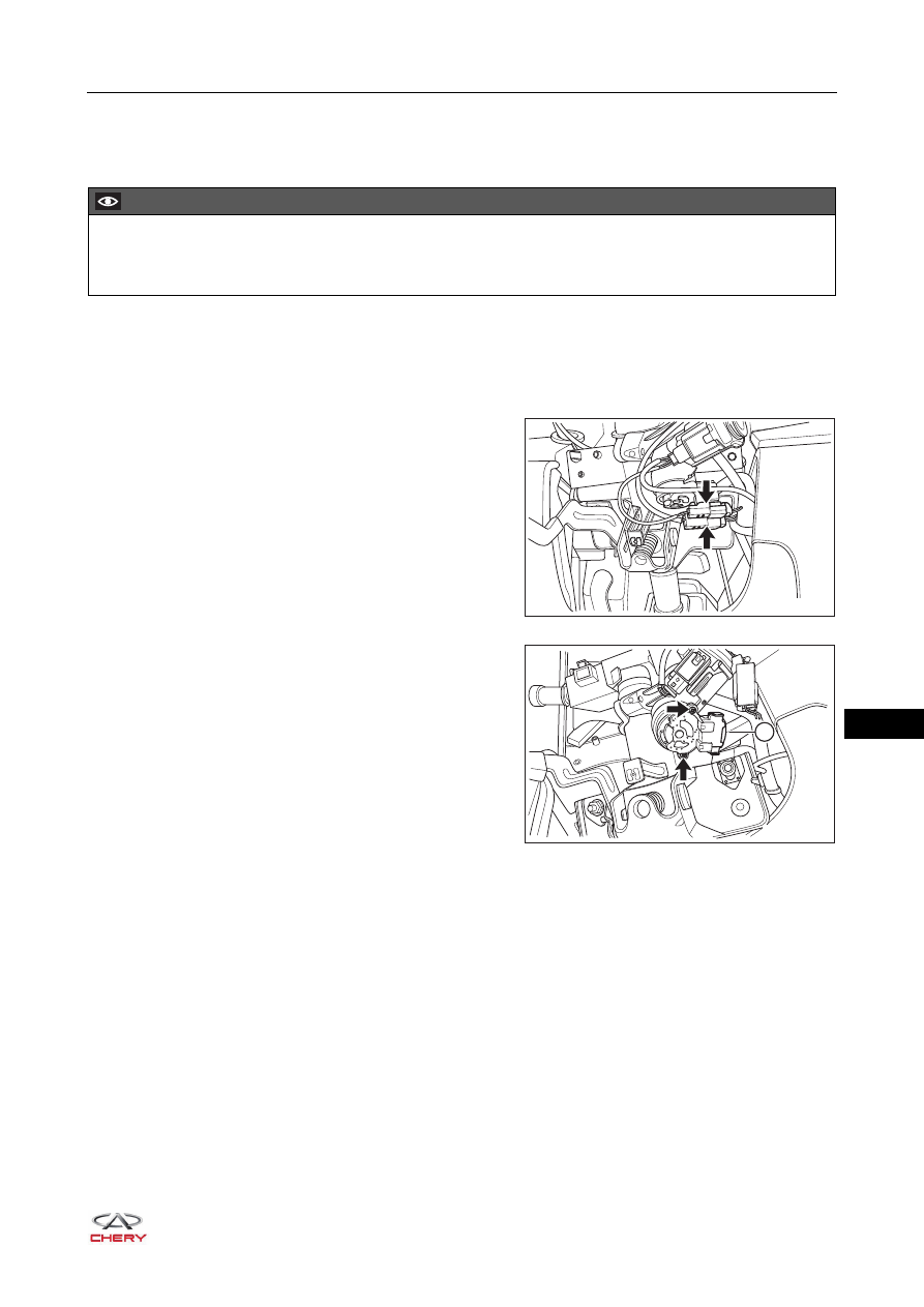
4. Remove the ignition starting switch.

a. Move the wire harness connectors (arrow) away from 

ignition starting switch.

b. Disconnect the ignition starting switch connector (1).
c. Remove the fixing screws (arrow) from ignition 

starting switch.

(Tightening torque: 13 ± 2 N·m)

d. Remove the ignition starting switch.

CAUTION

 Be sure to wear necessary safety equipment when repairing to prevent accidents.
 Try to prevent vehicle protector from being scratched during removal and installation.

RT21150140

1

RT21150150

15–

68

15

Inspection

1. Check for continuity of ignition starting switch.

Using ohm band of the digital multimeter, check for 
continuity of ignition starting switch according to the table 
below.

If result is not as specified, replace the ignition starting switch.

Installation

Installation is in the reverse order of removal.

1 2 3

4 5 6

-

+

RT21150160

Multimeter 

Connection

Switch 

Condition

Specified 

Condition

All terminals

LOCK

No continuity

Terminal 1 -

Terminal 3

ACC

Continuity

Terminal 1 -

Terminal 2

Terminal 1 -

Terminal 3

Terminal 2 -

Terminal 3

Terminal 5 -

Terminal 6

ON

Continuity

Terminal 1 -

Terminal 2

Terminal 4 -

Terminal 5

Terminal 4 -

Terminal 6

Terminal 5 -

Terminal 6

START

Continuity

15–

69

15

Engine Switch (w/ PEPS System)

Removal

1. Turn off all the electrical equipment and ignition switch.
2. Disconnect the negative battery cable.
3. Remove the combination switch cover (

See page 28-13

).

4. Remove the engine switch.

a. Disconnect the engine switch connector (arrow).

b. Detach 2 claws on engine switch in the direction of 

arrow as shown in the illustration, and remove the 
engine switch.

CAUTION

 Be sure to wear necessary safety equipment when repairing to prevent accidents.
 Try to prevent vehicle protector from being scratched during removal and installation.

RT21150170

RT21150180

15–

70

15

Inspection

1. Check for continuity of engine switch.

Using ohm band of the digital multimeter, check for 
continuity of engine switch according to the table below.

If result is not as specified, replace the engine switch.

2. Check engine switch indicator illumination.

Apply battery voltage between terminals of engine 
switch, check engine switch indicator illumination.

HINT:

 If positive (+) lead and negative (-) lead are connected 

incorrectly, the engine switch indicator does not come 
on.

 When battery voltage is too low, the engine switch 

indicator does not come on.

If result is not as specified, replace the engine switch

Installation

Installation is in the reverse order of removal.

RT21150190

ENGINE

START

STOP

1 2 3 4

5 6 7 8

-

+

Multimeter 

Connection

Switch 

Condition

Specified 

Condition

Terminal 1 -

Terminal 2

Not pushed

No continuity

Terminal 3 -

Terminal 2

Not pushed

No continuity

Terminal 1 -

Terminal 2

Pushed

Continuity

Terminal 3 -

Terminal 2

Pushed

Continuity

RT21150200

-

+

ENGINE

START

STOP

1 2 3 4

5 6 7 8

Measurement 

Condition

Condition

Specified 

Condition

Battery positive 

(+) → Terminal 4

Battery negative 

(-) → Terminal 2

Always

Come on 

(stamping word)

Battery positive 

(+) → Terminal 5

Battery negative 

(-) → Terminal 2

Always

Come on (amber)

Battery positive 

(+) → Terminal 8

Battery negative 

(-) → Terminal 2

Always

Come on (green)


Content   ..  181  182  183  184   ..