Chery Tiggo 5 (T21). Manual - part 181
 

  Index      Chery     Chery Tiggo 5 (T21) - service repair manual 2014 year


Search            


Content   ..  179  180  181  182   ..


Chery Tiggo 5 (T21). Manual - part 181


15–

59

15

a. Turn ignition switch off.
b. Disconnect the instrument panel fuse and relay box 

connectors I-007 and I-031.

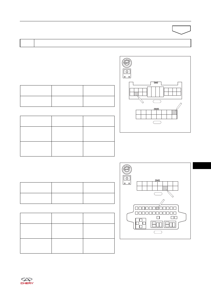
c. Check the wire harness between terminal E10 of 

instrument panel fuse and relay box connector I-031 and 
terminal J101 of PEPS controller connector I-029.
Check for Open

Check for Short

d. Check the wire harness between terminal 7 of instrument 

panel fuse and relay box connector I-007 and terminal 
J111 of PEPS controller connector I-029.
Check for Open

Check for Short

5

Check PEPS controller power supply circuit

NG

-

+

RT21150430

J101

J102

J103

J104

J105

J106

J107

J108

J109

J110

J111

J112

J113

J114

J115

J116

I-029

E20

E19

E18

E17

E12

E11

E10

E9

E4

E3

E2

E1

E8

E7

E6

E5

E16

E15

E14

E13

I-031

Multimeter 

Connection

Condition

Specified 

Condition

I-031 (E10) - 

I-029 (J101)

Always

Continuity

Multimeter 

Connection

Condition

Specified 

Condition

I-031 (E10) or 

I-029 (J101) - 

Body ground

Always

No continuity

I-031 (E10) or 

I-029 (J101) - 

Battery positive

Always

No continuity

-

+

RT21150440

J101

J102

J103

J104

J105

J106

J107

J108

J109

J110

J111

J112

J113

J114

J115

J116

I-029

1

2

3

4

5

6

7

8

9 10 11 12

13

85

85

87

87 30

87 30

30

86

86

85

86

14 15 16 17 18 19 20 21 22 23 24

25

27

26

I-007

Multimeter 

Connection

Condition

Specified 

Condition

I-007 (7) - I-029 

(J111)

Always

Continuity

Multimeter 

Connection

Condition

Specified 

Condition

I-007 (7) or I-029 

(J111) - Body 

ground

Always

No continuity

I-007 (7) or I-029 

(J111) - Battery 

positive

Always

No continuity

15–

60

15

a. Disconnect the CVT connector A (arrow).

b. Check the CVT connector A.

Repair or replace related wire harness or 
connector (instrument panel fuse and 
relay box - PEPS controller)

NG

6

Check CVT connector A

OK

RT21150451

Gearshift Position

Terminal No.

Specified Condition

P

1 - 7, 9 - 10

Continuity

R

7 - 8

N

2 - 7, 9 - 10

D

3 - 7

L

4 - 7

Repair or replace CVT connector A

NG

OK

15–

61

15

a. Disconnect the engine compartment wire harness 

connector E-067.

b. Check the wire harness between PEPS controller 

connector I-029 and engine compartment fuse and relay 
box connector E-067.
Check for Open

Check for Short

c. Check the wire harness between PEPS controller 

connector I-029 and CVT connector A E-050.
Check for Open

Check for Short

7

Check wire harness (instrument panel - engine compartment)

-

+

RT21150450

J101

J102

J103

J104

J105

J106

J107

J108

J109

J110

J111

J112

J113

J114

J115

J116

I-029

E-067

H8

H16

H7

H15

H6

H14

H5

H13

H4

H12

H3

H11

H2

H10

H1

H9

Multimeter 

Connection

Condition

Specified 

Condition

I-029 (J110) - 

E-067 (H5)

Always

Continuity

Multimeter 

Connection

Condition

Specified 

Condition

I-029 (J110) or 

E-067 (H5) - Body 

ground

Always

No continuity

I-029 (J110) or 

E-067 (H5) - 

Battery positive

Always

No continuity

-

+

RT21150460

J101

J102

J103

J104

J105

J106

J107

J108

J109

J110

J111

J112

J113

J114

J115

J116

I-029

E-050

6

4

2

1

5

3

8

7

9

10

Multimeter 

Connection

Condition

Specified 

Condition

I-029 (J110) - 

E-050 (9)

Always

Continuity

I-029 (J113) - 

E-050 (10)

Always

Continuity

Multimeter 

Connection

Condition

Specified 

Condition

I-029 (J110) or 

E-050 (9) - Body 

ground

Always

No continuity

I-029 (J113) or 

E-050 (10) - Body 

ground

Always

No continuity

I-029 (J110) or 

E-050 (9) - 

Battery positive

Always

No continuity

I-029 (J113) or 

E-050 (10) - 

Battery positive

Always

No continuity

15–

62

15

a. Disconnect the starter control connector E-014 and engine 

compartment fuse and relay box connector E-022.

b. Check the starter field wire harness.

Check for Open

Check for Short

a. Connect related wire harness connectors.
b. Connect the negative battery cable.
c. Turn ignition switch ON.
d. Connect X-431 3G diagnostic tester to Data Link Connector (DLC) to check if any DTC is detected.

Repair or replace wire harness 
(instrument panel - engine compartment)

NG

8

Check starter field wire harness

OK

-

+

RT21150470

1

L2

L1

E-014

E-022

Multimeter 

Connection

Condition

Specified 

Condition

E-014 (1) - E-022 

(L1)

Always

Continuity

Multimeter 

Connection

Condition

Specified 

Condition

E-014 (1) or 

E-022 (L1) - Body 

ground

Always

No continuity

E-014 (1) or 
E-022 (L1) - 

Battery positive

Always

No continuity

Repair or replace starter field wire 
harness

NG

9

Confirm DTCs

OK

System operates normally

OK

NG


Content   ..  179  180  181  182   ..