Chery S11 / Chery QQ. Manual - part 223
 

  Index      Chery     Chery S11 / Chery QQ - service repair manual


Search            


Content   ..  221  222  223  224   ..


Chery S11 / Chery QQ. Manual - part 223


               SQR7080 维修手册                                                                                          372 发动机机械部分


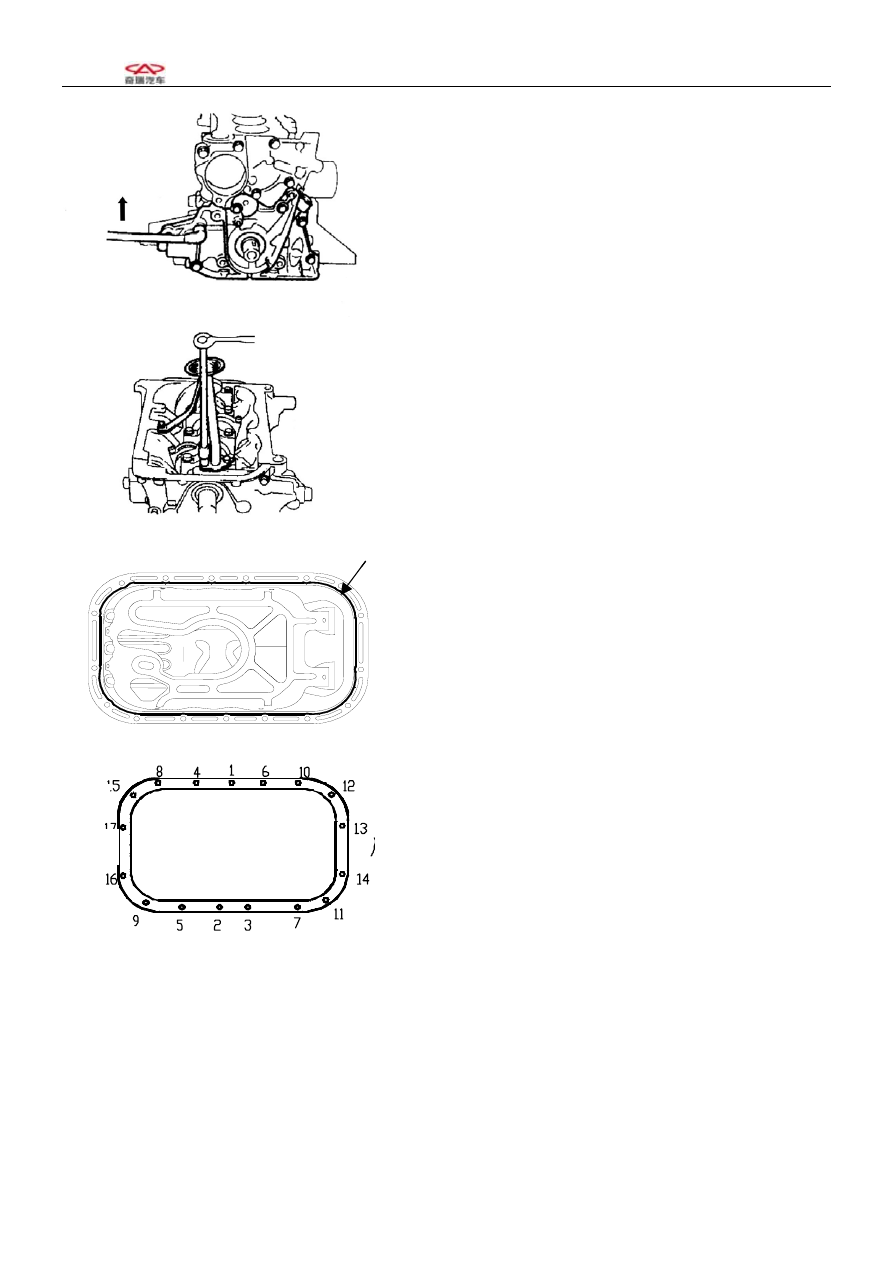
2. Assembling of new oil pump washer, oil pump 
assembly 
[Torque]  20±1.5N.m 


3. Installation of new lubricating oil collecting and 
filtering device, oil pump collecting and filtering 
device 
[Torque]   6±1N.m 


4.Assembling of oil pan 

 (1) Clear the mating surface with the cylinder 
body 
(2) Apply sealing silica before assembling 
[Grease] Letai 5699 
[Attention]   
·The liquid cushion with silica line diameter of 
ф3-4mm, without any broken section 
·Make the assembly in 15 minutes after the 
application of silica 


  (3). Tighten in the sequence shown in the right 

figure with the torque of 6±1N.m from the centre to 
the two sides 


front 

rea

front 

Rear

35 

               SQR7080 维修手册                                                                                          372 发动机机械部分


7. Crankshaft connecting rod mechanism   
7-1 Configuration diagram (Dismount and assemble the oil pump in the follow sequence) 


(1) Conneting rod cover 
(2) Connecting rod bearing bush 
(3) Piston and conneting rod assembly 
(4) Main bearing cover 
(5) Crankshaft 
(6) Crankshaft bush 
(7) Thrust washer 
(8) Cylinder block 
(9) No.1 compression ring 
(10)  No.2 compression ring 
(11) Oil 

ring 

(12) Piston 
(13) Connecting 

rod 

(14) Piston 

pin 

Non-reusable part 


36 

               SQR7080 维修手册                                                                                          372 发动机机械部分


7-2 Disintegration of crankshaft connecting rod 
mechanism 
1、Check the connecting rod axial clearance 

(1) Use centi-meter or feeler to measure axial 

spacing 

[Benchmark]:0.15-0.24mm 
[Limit]:0.30mm 


2、Check the connecting rod bush vertical clearance 

(2)Remove the bush cover 

[Attention]: Parts and components of various 
cylinders should be placed in good order. 
(1) Clean the bush and axle diameter 


  (4) Place clearance gauge on the connecting bearing 
diameter. 


(5) Tighten bush cover according to regulated torque 

torque: 40±2N.m                             


[Attention] Do not turn the crankshaft 
(6) Remove the bush cover, measure the maximum 
width of the spacing ruler 

[Benchmark]: 0.020-0.044 mm 
[Limit]: 0.07 mm 


37 

               SQR7080 维修手册                                                                                          372 发动机机械部分


(6) Replace the bush if width is beyond the limit. 
[Attention]
·In replacing the bushes, you should use the products 
of same brand and from the same manufacturer,which 
can accord with the request of clearings. 
3. Removal of connecting rod bearing cover and 
connecting rod bush 


(1)  The threaded section of the connecting rod bolt is 
to be equipped with protective sleeve to prevent from 
scraping the cylinder hoe and crankshaft connecting 
rod axle diameter. Then knock the piston connecting 
rod out with the handle of a hammer. 
[Attention] Put the parts and components of various 
cylinders in good order. 
 

(2) Use a caliper to measure the crankshaft axial 
clearance. If the axial clearance is above the limits, it 
is needed to replace the axial thrust washer or the 
crankshaft. 
[Benchmark]:0.02-0.22mm 
[Limit]:0.30mm 

Item 

Benchmark 

value 

Thickness of thrust 

face 

1.7

+0.15

-0.25


Connecting 
rod bush 

Connecting 
rod cover 

Lagging cover 

protective
sleeve


38 


Content   ..  221  222  223  224   ..