Chery S11 / Chery QQ. Manual - part 197
 

  Index      Chery     Chery S11 / Chery QQ - service repair manual


Search            


Content   ..  195  196  197  198   ..


Chery S11 / Chery QQ. Manual - part 197


  Chery    QQ    Maintenance Manual                                                      Chassis System


70


Section Two   Front Suspension Frame 

Maintenance of the front suspension frame 

I.


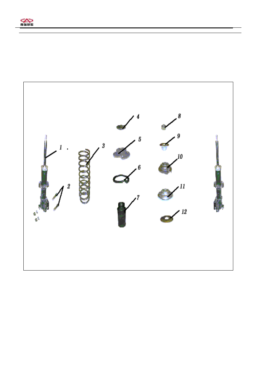
Configuration Diagram of Front Suspension Frame 


1

、 Dampener;    2、Joining bolt; 3、Spiral spring; 4、Thrust bearing; 5、Spring upper stand washer; 6、

Spring lower stand washer; 7

、Spacing block; 8、Screw nut;9、Washer; 10、External connection sleeve; 

11

、Dampening washer; 12、Thrust bearing stand 


  Chery    QQ    Maintenance Manual                                                      Chassis System


71


II. Removal and installation of the front 

balanced beam and the rubber sleeves 

for the balanced beam 

 Removal 

1

、Loosen the two fastening screw nuts of the 

supporting frame and car body. There is one 
supporting frame on either side.     
Attention: The fastening screws of the 
supporting frames and guard plates should be 
removed. 

2

、Loosen the two fastening screw nuts linking 

the balanced beam supporting frame with the car 
body. 
3

、 Remove the joining bolts of the balanced 

beam and the lower swinging arm. 

4

、Remove the balanced beam and the rubber 

sleeve. 


Steps for installation:


1.Do the installation by referring 


to the dismounting steps.


  Chery    QQ    Maintenance Manual                                                      Chassis System


86

2.Points of attention:


①  In the screw tightening process, the fastening 

bolts controlled by torque + corner tightening 
submission limits should be replaced after each 
action of loosening.


.

②  The screws should be tightened to the 

specified torques after the installation. 
 

III. Spiral spring and dampener 

(supporting column) 

IBefore removing the supporting column, 

check the performances of the supporting 
column 

Check and adjust the tire air pressure as specified; 
push sidewise and shake the front part of the car 
for 3—4 times with equal forces applied to each 
pushing. When the action of pushing and 
bouncing back takes place, pay attention to the 
resistance of the supporting column and the 
frequencies of the back bouncing of the car body. 
Compare the resistances as well as the 
frequencies of bounces for the columns 
(dampeners) on the left and right sides, which 
should be identical. If the supporting column 
(dampener) works normally, the car will stop 
immediately as soon as the hand-push forces are 
released or after the back bounces for 1—2 times.   

IIRemoval and installation of the front 

absorber assembly   
Removal 

1

、Remove the wheels. 

2

、 Remove the E-shaped ring for fastening the 

brake soft tube, and take off the tube from the   
 
supporting frame. 

3

、 Remove the two fastening bolts for the 

absorber and car frame. 
4

、 Remove the joining bolts for the absorber 

and the steering knuckle. 
5

、 Remove the absorber assembly. 


Steps for installation:


1.Do the installation by referring to the 


  Chery    QQ    Maintenance Manual                                                      Chassis System


87

dismounting steps. 


2.Points of attention:


①. In the screw tightening process, the fastening 

bolts controlled by torque + corner tightening 
submission limits should be replaced after each 
action of loosening. 

② .The screws should be tightened to the 

specified torques after the installation. 
 

IIIInspections 

1

Checking the dampener 

Check to see if there is any oil leakage on the 
dampener. If any, replace the dampener. Check 
the dampening force of the dampener. If not 
qualified, replace the dampener.   
Check to see if the thrust bearing is excessively 
worn, has any abnormal operational noise or is 
jammed one way or the other. Check to see if the 
lower stand of the spring has any cracks or 
deformation. Check to see if the spacing block is 
damaged. Check to see if the suspension reset 
spring spacing washer is worn, cracked or 
deformed. If so, replace the defective parts.   
 

Attention: When disposing the dampener, please 
follow the procedures described below. 

2

Disposal of the front dampener 

( 1 ) Stretch the dampener rod as much as 

possible. 

(2)Drill hole to discharge the air inside the 

dampener cylinder.. Drill a hole on the cylinder   
 
 
body as shown in the figure to discharge the air   
inside. 


  Attention:  The discharged air is harmless. But 
iron dusts may fly all around when the hole is 
drilled. 


  (IV)Dismounting and installation of   

absorption supporting columns, column 

parts and/or springs


1. If the installation fixtures are unable to be 
fastened onto the operation platform, they can be 
fastened in the bench vise. 
2. Install a pair of jaws with diameter matching 
that of the springs onto the spring compressor.


Removal


1. Loosen the spring compressor and place the 
jaws  


Content   ..  195  196  197  198   ..