Chery S11 / Chery QQ. Manual - part 196
 

  Index      Chery     Chery S11 / Chery QQ - service repair manual


Search            


Content   ..  194  195  196  197   ..


Chery S11 / Chery QQ. Manual - part 196


  Chery    QQ    Maintenance Manual                                        Chassis System


2Camber angle 
Under normal circumstances, the camber angle does not have to be adjusted after the car 
is equipped with the independent suspension system and wheel knuckles. In the case that 
the wheel camber angle is detected to have bias from the allowances due to some reasons, 
alignment can be made by way of adjusting the connecting screw nuts for the independ- 
 
 
ent suspension system and the knuckles. 

- 66 -     

(1)             (2) 


(1)   First check (visually) to see if there are any   
damages on the driving system parts and components 
before doing the alignment. Replace the damaged parts   
or components if there are any. The camber angle   
designed and set for the front wheels by the manufacturer 

Adjustment of


screw nut


cannot be adjusted; 


(2)  In the case that the front wheel camber angle is detected to exceed the allowed bias, 
loosen the connecting screw nuts for the front absorber and the knuckles, and move the 
wheel for proper alignments. 
 
3Toe-in 
Special four-wheel positioning testers should be used to test and adjust the toe-in. 
 
(1)  Make preparations prior to the adjustments as required by the tester. Use the steering 
wheel limiter available on the marketplace to fix the steering wheel in the straightforward 
direction (the steering wheel must be in the center position±5 degrees, and the lower 
clamping flange of the steering axle should keep horizontally leveled). 
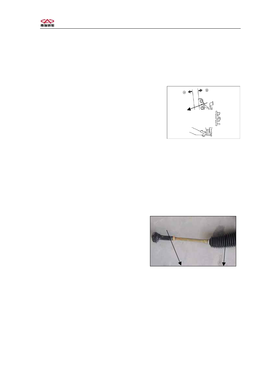
(2) Loosen the locking screw nuts (1) of the   
steering horizontal drawbar. 


(3) Remove the elastic protective clip ring (2)   
with a pair of pliers.   


Attention: Replace the clipping ring if it is not elastic enough. 
(4) Turn the toe-in adjustment rod to adjust the length as 
  needed till it meets the specified value. 
(5) Tighten the screw nut (1) and re-install the protective elastic clip ring (2), check to 
see if the locking screw nut is tight enough and if the position of the protective sheath is 
correct or not. 
(6) Upon completion of the adjustments for the front wheel toe-in, check to see if the 
steering wheel is leveled. If not, loosen the locking screw nut of the steering wheel and 
adjust the steering wheel to the leveled position. Tighten the locking screw nut till it 
meets the torque specification (30±3Nm). 


  Chery    QQ    Maintenance Manual                                        Chassis System


4Check and test the front wheel steering angle  
After the horizontal drawbar joint is replaced or the toe-in is adjusted, the steering angle 
should be checked. If it fails to meet the specifications, the length of the left and right 
horizontal drawbars should be checked and adjusted. 


IV. The toe-in and camber angle of the rear wheels cannot be adjusted. 

Check the camber angle and toe-in of the rear wheels. If they fail to be in the specified 
limits, check to see if there are any deformed parts. Replace the defective parts. 


Section Four: Guide to Trouble-Shooting 


Problem Possible 

cause 

Countermeasures 

Excessive tear-and-wear 

or unevenly distributed 

tears and wears of tires 

As indicated later 


Tears and wears of tires 

ahead of scheduled 

operational life 

Incorrect tire pressure 

Incorrect wheel positioning 

parameters 

Adjustment 

Adjustment 

Tire noises 

Incorrect tire air pressure 

Tears and wears of tire 

Adjustment 

Check, adjustment, 

replacement 

Road surface noises or 

vibration of car body 

Insufficient tire pressure 

Imbalance of tires 

Deformed rim section or tire 

Unevenly distributed tears 

and wears of tire 

Adjustment 

Adjustment 

Repair or replacement 

Check, adjustment, 

replacement 


- 67 -     

  Chery    QQ    Maintenance Manual                                        Chassis System


Vibration up 
and down of 
steering wheel 

Excessive bias of tire and rim section 
Loose wheel screw nuts or axle heads 
Imbalance of tires 
Broken or damaged engine suspension 
rubber 
Broken or damaged gear box supporting 
stand rubber 

Replacement 
Tightening 
Adjustment 
Replacement 
 
Replacement 

Circling 
vibration of 
steering wheel 

Excessive bias of tire and rim section 
Loose wheel screw nuts or axle heads 
Imbalance of tires 
Unevenly distributed tears and wears of tire 
Insufficient tire air pressure 
Broken or damaged front wheel bearings 
Faulty steering system 
Faulty suspension system 

Replacement 
Tightening 
Adjustment 
Check 
Adjustment 
Replacement 
Check 
Check 

Lopsidedness 
of steering 
wheel 

Abnormal tire air pressure 
Excessive tears and wears of tires or 
unevenly distributed tears and wears 
Faulty steering system 
Faulty braking system 
Faulty suspension system 

Adjustment 
Check 
 
Check 
Check 
Check 

Unstable 
movement 

Inconsistent air pressures for the tires on both 
sides 
Deformed rim section or tire 
Loose wheel screw nuts 
Faulty steering system 
Faulty suspension system 

Adjustment 
 
Repair or replacement 
Tightening 
Check 
Check 

Lopsided 
braking 

Unbalanced tire air pressures on both sides 
Faulty braking system 

Adjustment 
Check 

Heavy steering 
wheel 

Insufficient tire air pressure 
Faulty steering system 
Faulty suspension system 
Incorrect wheel positioning parameters 

Adjustment 
Check 
Check 
Check 

Poor operation 
of steering 
wheel to return 
to straight for- 
ward direction 

Insufficient tire air pressure 
Faulty steering system 
Faulty suspension system 
Incorrect front wheel main pin backward 
tilting 

Adjustment 
Check 
Check 
Adjustment 


- 68 -     


  Chery    QQ    Maintenance Manual                                                      Chassis System


69


Chapter Three  Suspension System 

Section One   Specifications


Tautness for Various Fasteners


Part No. 

Description 

Quantity

Installation position 

Torque 

(N·m)

Q150B1010 Connecting bolts 

Braking tube and clamp       

15±2 

Q151B1255 Bolts 

Rear absorber and rear shaft M12×1.25, 
rear shaft horizontal supporting rod and car 
body 

65±5 

Q151B1285  Bolts 

Rear towing arm and rear shaft 

83±7 

Q151B1290  Bolts 

Lower swing arm and car body M12×1.25

83±7 

Q151C1040  Bolts 

Lower swing arm and knuckle M10×1.25 

60±5 

Q151C1080  Bolts 

Lower swing arm and car body M10×1.25

65±5 

Q151C1255 Bolts 

Front sliding column and knuckle 
M12×1.25 

84±6 

Q1421030 

Hexagon head bolts and 
spring washer assembly 

Supporting frame and car body M10×1.25 

40±5 

Q1421035 

Hexagon head bolts and 
spring washer assembly 

Supporting frame fixing stabilizing rod 
M10×1.25 

45±5 

Q1440616  Screws 

Supporting frame and car body 

8±2 

CQ32608 

Screw nuts 

Front sliding column and car body 

25±2.5

CQ32610 

Locking screw nuts 

Suspended supporting frame and rear 
transit supporting frame M10×1.25 

60±5 

CQ32612 Screw 

nuts 

Stabilizing rod and lower swing arm 
M12×1.25 

65±5 

Q1420820 

Hexagon head bolts and 
spring washer assembly 

Brake and rear shaft 

24±2 

Q361B12 Screw 

nuts 

10 

Rear absorber and car body; rear towing 
arm and car body; rear shaft horizontal 
supporting rod and car body; rear shaft 
horizontal supporting rod and rear shaft 

55±5 

S11-330120

Screw nuts with washers 

Rear towing arm and rear shaft 

80±5 


Content   ..  194  195  196  197   ..