Chery S11 / Chery QQ. Manual - part 195
 

  Index      Chery     Chery S11 / Chery QQ - service repair manual


Search            


Content   ..  193  194  195  196   ..


Chery S11 / Chery QQ. Manual - part 195


  Chery    QQ    Maintenance Manual                                        Chassis System


11Installation 

block

outboa

block

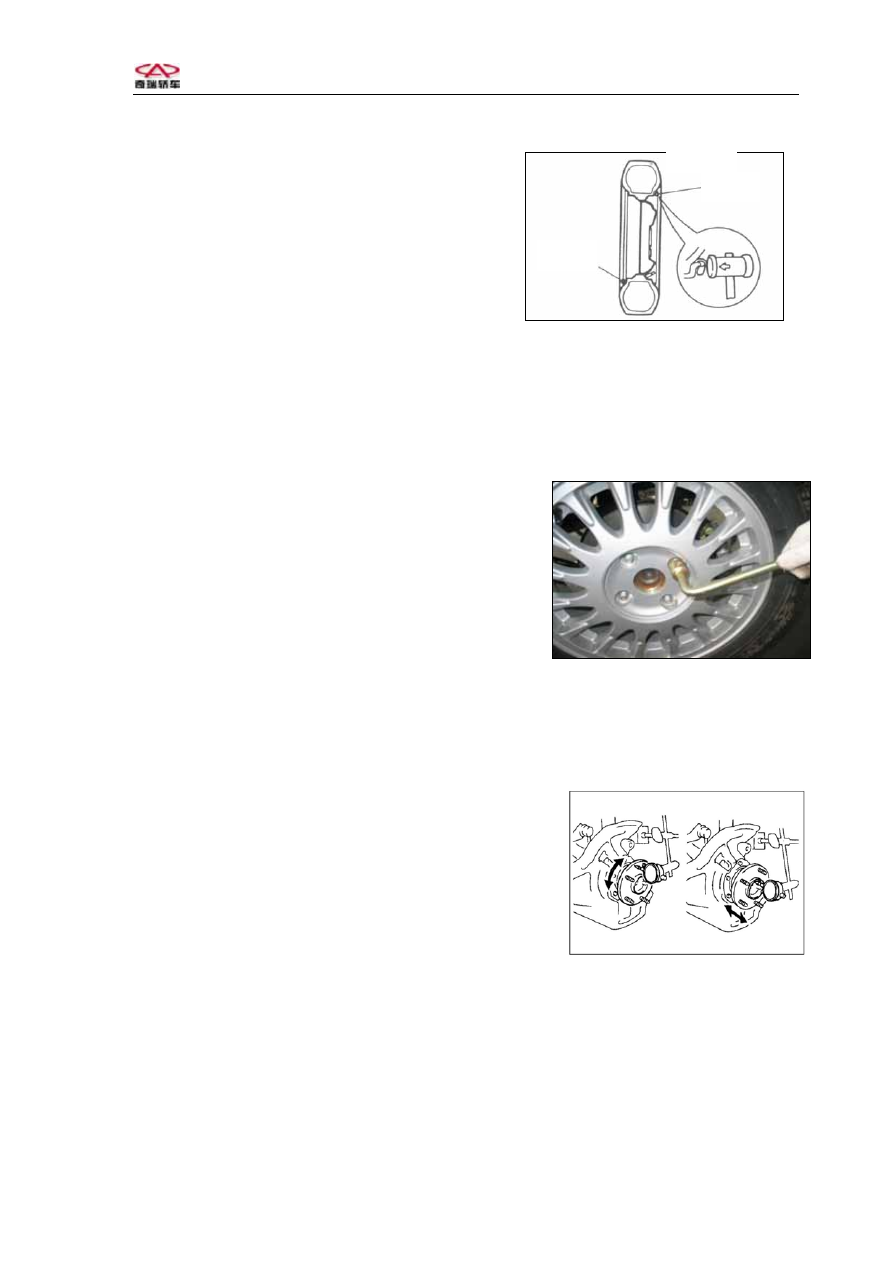
(1)  When making the assembly of the 
wheels and tires, first fix the wheel screws onto   
the hubs manually and tighten them slightly.   
Then use special tools to tighten the screws in   
the diagonal sequence till the specified torque 
of 110±10N.m is applied. It is not allowed to   
use impact wrenches that might cause damages   
to the wheels, or insufficient tightness or excessive 
tightness. It is not allowed to apply lubricating grease onto the wheel screws. (For the 
completed assembly of wheels and tires, the wheel screws should be re-tightened after the 
car runs for 100km so that the specified torque is assured. The checks on the torque of the 
fixing screws are one of the routine maintenance items). 


(2)    When tightening the screw nuts, the   
cross approach is applied. The extent of tightness   
should be close to each other, and the wheels should 
be able to turn freely. When the final tightening is 
made, the wheels should be positioned on the ground. 


(3)Install the decorated covers or place the decorative covers as needed. When the 
clip-type decorative covers are installed, they should be driven in either with hands or by 
way of rubber hammering tools. 
 

III.    Checks on the looseness of wheel bearings 

1、Check the axial spacing of the bearings 
Maximum: 0.05mm 
2、Check the bias of the bridge hub 
Maximum: 0.05mm 


IV. 

Checks on the looseness of front suspension system   

V. 

Checks on the looseness of turning transmission rod system 

VI. Checks on ball joint looseness 

VII.  Checks on the normal performances of absorbers 

- 62 -     

  Chery    QQ    Maintenance Manual                                        Chassis System


1、Check to see if there is any oil leakage; 
2、Check to see if there are any tears and wears of the assembly sheaths; 
3、Check the resistance of the absorbers. Make proper replacement if any incompliance is 
detected. 


Section Two: Positioning of Rear Wheels 


It is recommended to use the four-wheel positioning device for the chassis of this car model, 
which applies the positioning approach by way of axis thrust. 
In the position adjustments by way of axis thrust, the toe-in of the rear wheels may have 
impacts upon the toe-in of the single front wheel. Therefore, when doing the four-wheel 
positioning, the adjustments of the rear wheels are generally done before the adjustments of 
the front wheels. Besides, the camber angle of the rear wheels is adjusted before adjusting 
the toe-in angle, followed by the adjustments of the camber angle and toe-in angle of the 
front wheels. 


I. Measure the height of the car 

Before measuring the height of the car, first increase the air pressure of the tires to the 
specified value (make sure that the air pressures for the left and right tires should be 
identical). 


front


1The front measuring point 
The height of the center point from the ground to the 
link screw nut for the lower control arm assembly and 
the front turning joints is to be measures. The car 
body height of the left and right wheels should be 
basically the same. 


2The rear measuring point 


back

The height of the center point from the ground to link   
screwnut for the rear bridge and the absorber is to be 

measured.  

The left and right body heights should be basically the same. 


- 63 -     

  Chery    QQ    Maintenance Manual                                        Chassis System


Attention:
 Before testing and checking the wheel positioning, the car should be first 
adjusted to the specified height. 
If the car height does not meet the specification, check the front and rear suspension 
systems of the car to see if there are any damages or deformations. 
   

II. Place the wheel positioning device or the positioning tester on the 

wheel


1、 

Install the instruments in the way as specified by the   

manufacturer of the devices; 

2、 

Make tests and adjustments on the car as required by 

the equipment. The specifications for the positioning are 
as follows: 


Rear wheel assembly toe-in

20

1

±40

1

Single rear wheel toe-in 

10

1

±20

1

Rear wheel camber angle 

0

1

±20

1

Thrust angle 

-13

1

~+10


Section Three: Front Wheel Positioning 

I. Measure the car height 

Do the measuring and adjustments in the same procedures as the ones for the car 

height measurements for rear wheel positioning. 
 

II. Place the wheel positioning device or the positioning tester on the 

wheel 

 
Install the instruments in the way as specified by the 
manufacturer of the devices. 


- 64 -     

III. Check and adjust the front wheel main pin backward tilting angle, 

  Chery    QQ    Maintenance Manual                                        Chassis System


main pin interior falling-in angle, wheel camber angle as well as the wheel 

toe-in and steering angle 

Specifications: The requirements for the front wheel positioning are as follows: 
 

Main pin backward tilting angle 

3°.15

1

±30

1

Front wheel camber angle 

1°±30

1

Single front wheel toe-in angle 

10

1

±10

1

Steering angle 

Inner side:35

0

±4°  

Outer side:31

0

±4 

 
Note:  
The backward tilting angle is adjusted before adjusting the camber angle and the 
toe-in angle. 


1Main pin backward tilting angle 
This angle is assured by way of the designed configuration, which makes the operational 
adjustments unnecessary. 


The impacts of backward tilting angle 

The major function of the backward tilting angle is to keep the car moving in the 

straightly forward direction. If the backward tilting angle is positive, the inner side of the 
car will be lowered when the front wheel turns in directions, which results in the uprising 
of the chassis. That will increase the loads onto the knuckles. If the backward tiling angles 
of the two wheels are identical, the car will be back to the straightforward  direction after 
turning the directions. The increase of the positive backward tilting angle will increase the 
stability of the steering wheel, but the turning forces will be increased as well. The decrease 
of the positive backward tilting angle will reduce the stability of the steering wheel but the 
turning forces will become reduced. The extent of the backward tiling angles will not have 
impacts upon the tears and wears of the tires. They are used to stabilize the driving 
directions and ensure the automatic returning to the straightforward direction after turning. 
If the car is equipped with the traditional mechanic steering devices, the backward tilting 
angle will be very small or even tending to be in the negative, which makes the turning of 
direction easier. If the car is equipped with the dynamic steering device, the backward tiling 
angle is generally set to be relatively large positive angle, which allows the driver to feel 
the turning of directions. The increase of the positive backward tiling angle will increase 
the forces for turning, and increase the stability in straightforward movement of the car. 


- 65 -     


Content   ..  193  194  195  196   ..