Chery S11 / Chery QQ. Manual - part 149
CHERY SQR7080 EZ Drive SERVICE MANUAL
MECHANICAL TRANSMISSION
– ELECTRONICALLY CONTROLLED HYDRAULIC UNIT
Tightening torque (unit: DAN.M)
M8 bolt for electric pump set
2.4
M10 bolt for electric pump set
4.4
Nut for drive mechanism module
2.1
Pin for drive mechanism module
0.8
High-press pipeline coupler
1.4
Before maintaining the entire automated mechanical
transmission, use a special repair tool to remove the
energy storage.
When doing this, comply with the control procedure
described
in
the
section
of
“ENERGY
STORAGE”.
Once accomplishing this procedure, the buzzer will
make a buzzing sound.
In order to confirm that the pressure therein has
dropped into the specified range, refer to the section
of “PR018 HYDRAULIC SYSTEM” to know the
standard resultant pressure range.
If you fail to do this, repeat the control procedure
described in the section of “ENERGY STORAGE”
until the pressure becomes very low and it has no
risk to remove the high-pressure pipeline.
Removal:
Before removing the hydraulic unit, you shall
remove its seat stand and the gearbox.
With regard to how to remove the seat stand, refer
to Chapter 21 of Service Manual 305.
When removing the gearbox, you shall be careful
not to damage the hydraulic unit.
Remove the electronically controlled hydraulic
unit of the transmission.
Remove the clutch fork cable.
Remove the connector of the original speed sensor.
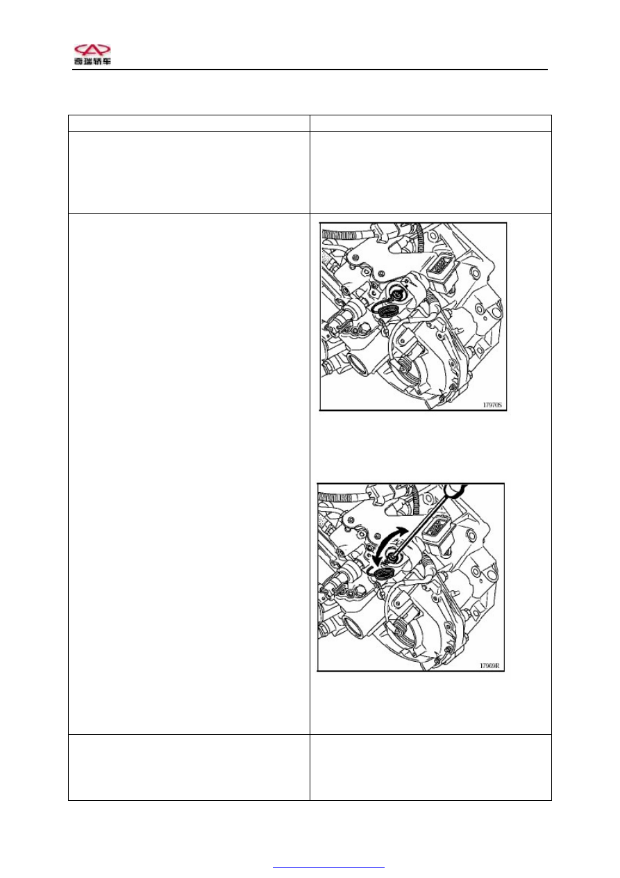
In order to loosen the speed transmission control
shaft, rotate the shaft a quarter turns by using a
screwdriver.
Lock the control shaft.
The clearance on the shaft should be aligned with
the mark.
Loosen the control shaft.
The clearance on the shaft and the mark are at the
right angle.
Handle used to fix the electronically controlled
hydraulic unit.
Put two half-moon parts and circlip into the control
shaft groove.
Smear MOLYKOTE 33 (moderate) onto the two
half-moon parts.
PDF created with pdfFactory Pro trial version