Chery S11 / Chery QQ. Manual - part 113
 

  Index      Chery     Chery S11 / Chery QQ - service repair manual


Search            


Content   ..  111  112  113  114   ..


Chery S11 / Chery QQ. Manual - part 113


Chery QQ Service Manual     


Mechanical Part of SQR 472Engine


21 

clearance once again: 

Cylinder 1 

Cylinder 2 

Cylinder 3 

Cylinder 4 

IN 

EX 

IN 

EX 

IN 

EX 

IN 

EX 

— 

— 

— 

— 

O   


If  the  clearance  exceeds  the  standard  value,  adjust  it  by 

replacing the adjustment gasket. 

Notice:  The  position  at  which  the  measurement  result 

exceeds  the  standard  value  as  well  as  the  measurement 

result should be recorded. 


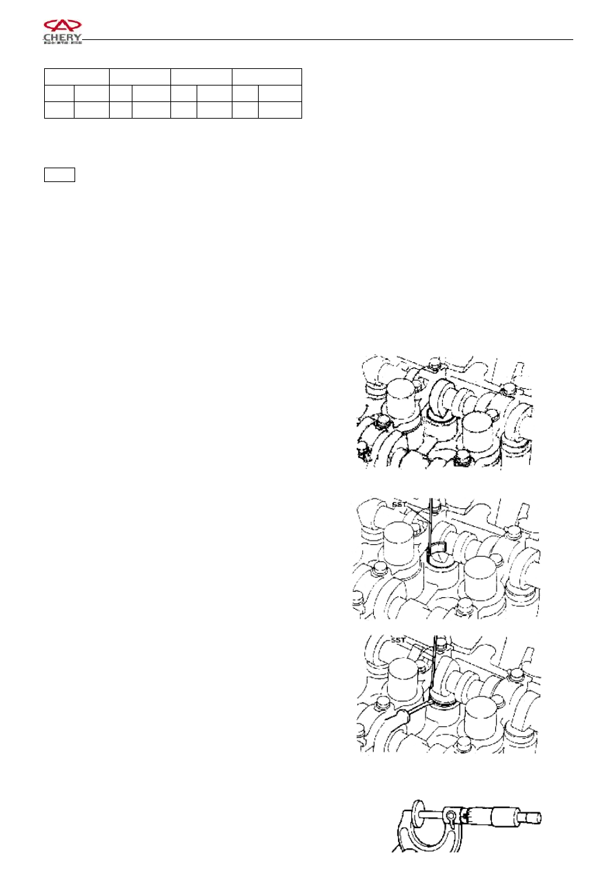
4.4.1    Rotate the camshaft and  make the cam head  of the 

cylinder  which  exceeds  the  standard  value  faces  upwards 

and the opening of the valve tappet face inwards.   


4.4.2    Rotate  the  crankshaft  and  press  down  the  valve 

tappet with the crown head of the cylinder cam. 


4.4.3    As indicated in the right figure, put special tools on 

and around the valve tappet from the inside of the cylinder 

head, and then rotate the crankshaft so that the crown head 

of  the  cam  face  upwards.  Press  the  valve  tappet  with 

special tools and hold on. 


4.4.3.1 

Pry  out the adjustment  gasket with screw  driver, 

remove the gasket inside with magnet. 


4.4.3.2 

Adjust  the  thickness  of  adjustment  gasket  with   


Chery QQ Service Manual     


Mechanical Part of SQR 472Engine


22 

micrometer caliper. 


4.4.3.3 

Select  the  gasket  on  the  basis  of  the  standard 

value of valve tappet 

①  Intake valve 

Select  gasket  thickness  =  Unload  thickness  + 

(Measured valve clearance -0.25mm) 

②  Exhaust valve 

Select  gasket  thickness  =  Unload  thickness  + 

(Measured valve clearance -0.25mm) 


[Reference]  The  32  kinds  of  gasket  with  different 

thickness are listed in the following table: 

2.18


2.40


2.62


2.20


2.42


2.64


2.22


2.44


2.66


2.24


2.46


2.68


2.26


2.48


2.70


2.28


2.50


2.72


2.30


2.52


2.74


2.36


2.58


2.80


2.32


2.54


2.76


2.38


2.6


4.4.3.4 

Adjust  the  valve  clearance  with  selected 

adjustment gasket. 

Notice: Install the adjustment gasket with its identification 

mark facing downwards. 


4.4.3.5 

Rotate  the  crankshaft  so  that  the  crown  head  of 

the  cam faces downwards and presses down the the valve. 

Pick up the special tool. 

4.4.3.6 

Rotate the crankshaft for 2-3 rounds and confirm 

once  again  the  valve  clearance.  If  it  is  still  beyond  the 

scope  of  standard  value,  adjust  and  inspect  the  valve 

clearance according to the operation specified in 4.1-4.4. 


3)  Cylinder Head 

1.  Structure Diagram 


Low


Chery QQ Service Manual     


Mechanical Part of SQR 472Engine


23 


Spark plug 20±1Nm   

Cylinder Head 

Weather Strip I 

Cylinder cushion 

Adjustment gasket 

Valve tappet 

Valve spring retainer 

Valve spring seat 

Valve Spring 

10  Intake valve 

11  Exhaust valve 

12  Valve oil seal 

13  Valve seat 

14  Valve guide 


2.  Disassembly 

2.1  Disassembly of spark plug 


2.2  There are 8 boltes on the cylinder head. In the course 


Components  which  may  not  be 

reused


Chery QQ Service Manual     


Mechanical Part of SQR 472Engine


24 

of the assembly of cylinder head, slowly tighten these bolts 

in  the  order  as  indicated  in  the  right  figure  for  several 

times untill ther are tightened properly.   

Notice:  Remove  the  cylinder  head  bolts  with  a  torque 

socket wrench in the contrary order.   


2.3    Disassembly  of  cylinder  head  and  cylinder  head 

gasket 

Notice: The cylinder head gasket is nonreusable. 


2.4    Disassembly  of  valve  adjustment  gasket  and  valve 

tappet 

2.5  Disassemble  the  valve  spring  retainer  lock,  spring 

retainer,  spring  seat,  valve  spring,  intake  valve,  and 

exhaust Valve etc with special tools. 

2.6  Disassembly of valve oil seal and valve spring gasket 


2.7    Cleanup 

2.7.1    Clean the carbon dust on the valve. 

2.7.2    Clean  the  bottom  surface  of  cylinder  head  and  the 

surface of intake and exhaust manifold with scraper knife. 

Notice:  The  surface  of  the  cylinder  head  may  not  be 

scratched in the course of cleanup. 

Do not pollute the intake port and water passage. 


3.  Routine Inspection 

3.1  Cylinder Head 

Measure  the  flatness  at  each  point  with  ring  gauge  as 

indicated in the figure. 

Cylinder head: 0.10mm 

Surface of intake/exhaust manifold: 0.10 mm。 


3.2    Valve Spring 

3.2.1    Measure  the  square  degree  of  valve  spring  with 

square. Replace if it exceeds the specified value. 

Limit:    1.2mm 


Content   ..  111  112  113  114   ..