Chery S11 / Chery QQ. Manual - part 112
 

  Index      Chery     Chery S11 / Chery QQ - service repair manual


Search            


Content   ..  110  111  112  113   ..


Chery S11 / Chery QQ. Manual - part 112


Chery QQ Service Manual     


Mechanical Part of SQR 472Engine


17 

2.7.1    Measure the camshaft with micrometer caliper. If it 

is below to the specified limit, replace with a new one. 

Camshaft journal                                                  Unit: mm 

EF 

                          Type 

Item 

ZL, RL 

GL, GS, ZS 

IN 

φ23.0

-0.02

-0.033


Standard value 

EX 

φ23.0

-0.02

-0.033


IN 

φ22.9 

Limit: 0.10 

EX 

φ22.9 


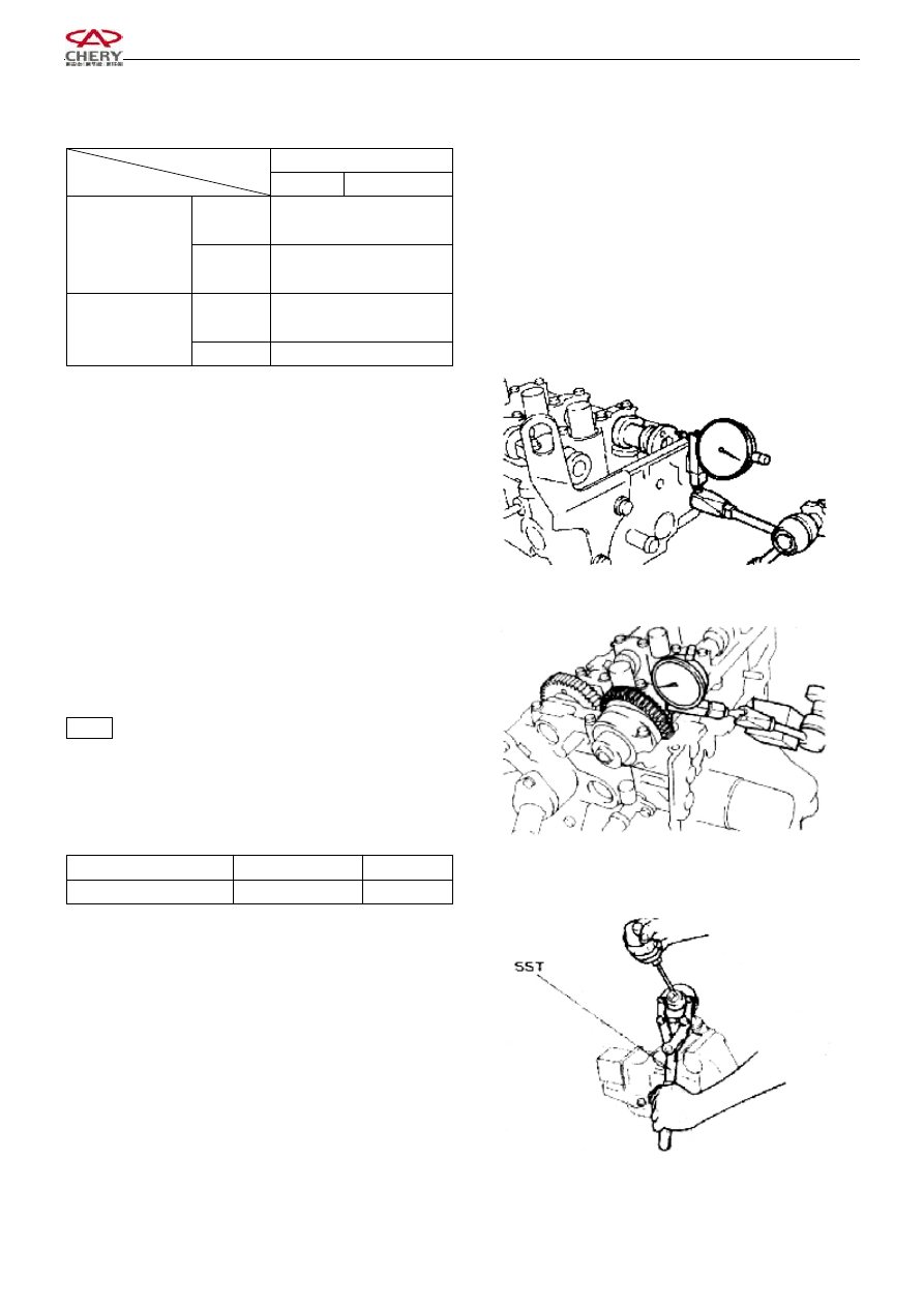
2.7.2 

Inspection of camshaft axial clearance 

(1)    Replace the camshaft  when the axial clearance value 

measured  with  dial  gauge  exceeds  the  standard  value.The 

axial clearance of intake camshaft is 0.1~0.170mm. 

The axial clearance of exhaust camshaft is 0.1~ 0.173mm. 

Limit: 0.18mm. 


2.7.3    Inspect  the  clearance  of  the  engaging  tooth  of 

camshaft 

(1)    Install the camshaft into the cylinder head. 

(2)    Confirm  the  mark  forwards  on  the  bearing  cap  as 

well as the axle number, and then tighten the bolts. 

(3)    Measure the clearance of engaging tooth of the intake 

camshaft with dia indicator. 

Notice: ·Measure at 4 points on the circle of the piston 

·Turn the intake camshaft with special tools. 
·Make  sure  that  the  marks  on  the  driven  gear  and 

the driving gear of the camshaft match with each 

other. 

Inspect the clearance of the engaging tooth of camshaft: 

Item 

Standard value 

Limit 

Single tootj 

0.04-0.13 

0.30 


3.  Installation 

3.1  Under the circumstance that special tools are used: 

3.1.1 

Fix  the  2  holes  (φ6)  of  the  camshaft  gear 

assembly with special tool. 

3.1.2 

Rotate  the  driven  gear  to  the  right  with  special 

tool  and  tally  the  mark  hole  of  driven  gear  with  that  of 

camshaft driving gear, or their marking way complies with 

each  other,  fix  the  driven  gear  with  bolts.(Thread:  M5; 

Thread pitch: 0.8) 


For Fixing 


Chery QQ Service Manual     


Mechanical Part of SQR 472Engine


18 

3.2  Under  the  circumstance  that  special  tools  are  not 

available: 

3.2.1 

Screw the M6 bolts into the camshaft driven gear 

at  the  position  indicated  in  the  right  figure.  Insert  a 

screwdriver  into  the  gap  between  the  M6  bolt  and  the 

camshaft  journal  and  trun  the  driven  gear  rightwards  so 

that  the  fitting  mark  of  the  2  gears  match  with  each  other 

or the tooth head of the 2 gears accord with each other, and 

then fix the driven gear with bolts (M5×0.8). 

Notice:  Don’t damage the journal, adjust the operation. 


3.3  Assembly of camshaft 

Notice: Pay attention to the axial clearance of the camshaft 

3.3.1    Spread grease on the gear of camshaft and the axial 

of cylinder head. 

3.3.2    Remove the fixing bolts for camshaft driven 
gear after mounting the camshaft.


3.3.3    Mount  the  camshaft,  align  the  timing  mark  as  can 

be seen from the right picture 


3.3.4    Spread  oil  fully  on  the  cam  of  camshaft  assembly, 

gears and axial of cylinder head. 


3.4  Tighten the camshaft bearing cap by the order of right 

picture. 


3.5  Screw  off  the  fixing  bolts  for  driven  gear  of  intake 

camshaft assembly. 


Timing Mark 

Gear 

of 

Exhaust 

Gear of Intake camshaft


For Fixing 

Bolt 


Chery QQ Service Manual     


Mechanical Part of SQR 472Engine


19 

3.6    Assembly of camshaft cove 

Spread  sealant  on  the  position  (slot)  of  camshaft  cover  as 

can be seen from the right picture. 


3.6.1    Assembly of Camshaft Cover 

Tighten  the  bolts  in  the  order  as  indicated  in  the  right 

figure and with the specified torque.   


3.6.2    After  spreading  oil  on  the  blanking  aperture  of 

cylinder head and the  mounting surface of blanking cover, 

press the blanking cover with special tool. 

Notice:·The  blanking  cover  should  be  installed  in  the 

direction as indicated in the right figure. 

·  After  being  pressed,  the  blanking  cover  should  be 

1±1mm  higher  than  the  surface  of  thecylinder 

head. 


3.7    Spread the edge of the camshaft oil seal with oil, and 

press  it  into  the  cylinder  head  with  M10  bolt  (length: 

50-60mm) and special tools.   

Notice:·  If  the  oil  seal  is  reused,  spread  it  with  oil  before 

pressing it into the cylinder head. 

· After removing the bolt, knock it with hand so as to 

inspect and confirm it. 


3.8    Assembly of camshaft timing gear 

After spreading sealant on the bolt, prevent it from rotating 

with  special  tool  and  screw  down  the  bolt  of  camshaft 

timing gear in specified torque. 

Torque:  100±5N.m 


Notice:    Process the special tools as indicated in the right 

figure before using them. 


Glue Spread Line 

Outside 


Chery QQ Service Manual     


Mechanical Part of SQR 472Engine


20 


3.9  Installation of cylinder head cover 

3.9.1  The  old  cushion  of  the  timing  belt  cover  which 

contacts  the  cylinder  head  cover  should  be  removed 

completely. 

3.9.2    Put  the  new  cushion  into  the  gloove  of  the  timing 

belt cover accurately. 

3.9.3    Mount  the  cylinder  head  cover  on  the  cylinder 

head, and tighten the 8 bolts in the order as indicated in the 

right figure and with the specified torque.   

Torque:  6±1N.m       


4  Inspection of valve 

4.1    Standard valve clearance: 

IN 

0.18±0.05 

Valve clearance 

EX 

0.25±0.05 


4.2


Make  sure  that  the  timing  mark  on  the  camshaft 

driving  gear  is  aligned  with  that  on  the  camshaft  driven 

gear. 


4.3    Inspect the valve clearance as specified in the figure 

below with the feeler gauge 


Cylinder 1 

Cylinder 2 

Cylinder 3 

Cylinder4 

IN 

EX 

IN 

EX 

IN 

EX 

IN 

EX 

— 

— 

— 

— 


4.4  Rotate  the  camshaft  for  a  round  to  the  position  as 

indicated  in  the  figure,  and  then  measure  the  valve 


Timing 

Gear 

of 

Exhaust 

Gear 

of 

Intake 


Content   ..  110  111  112  113   ..