Chery S11 / Chery QQ. Manual - part 64
 

  Index      Chery     Chery S11 / Chery QQ - service repair manual


Search            


Content   ..  62  63  64  65   ..


Chery S11 / Chery QQ. Manual - part 64


Chery QQ Service Manual                              BCM Computer Control System   


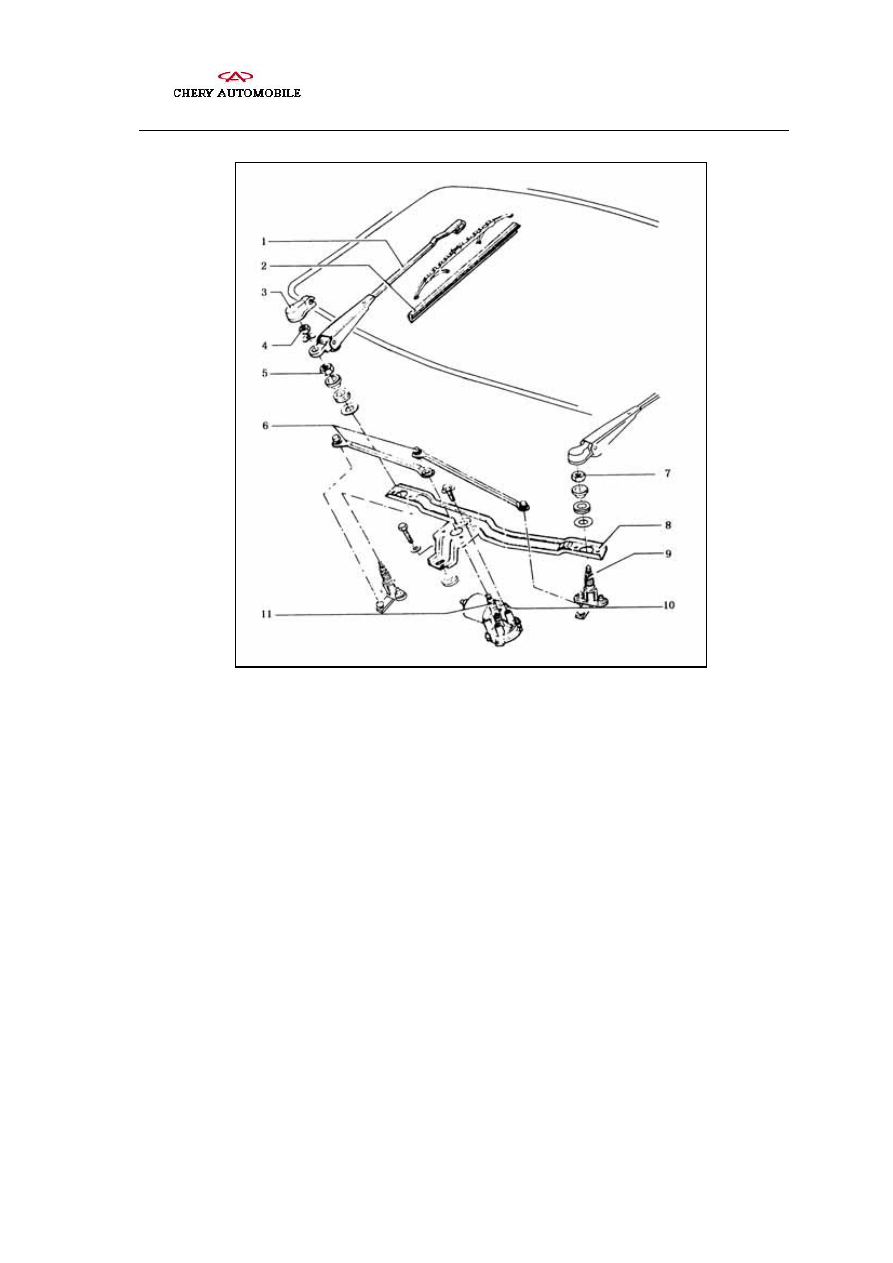
Structure of the wiper 

1- wiper arm    2- wiper rubber strip    3- protective cover   

4、5、7- nuts   6-  swing link  8- 

abutment

 9- journal     

10- motor  11- crankshaft 

     
The circuit system for the wiper and wash equipment is shown in the figure. If the 

start-up switch is turned on, by switching the wiper switch between the positions thereof, 

the power supply controlled by the start-up switch can be connected directly to the wiper 

motor through the fuse (fast position) or can actuate the motor through the relay (slow 

position, intermittent position and water injection position).     


When the wiper switch is in its lowest position, the wiper is out of operation. When the 

wiper switch is turned to the “2” position, the wiper operates in intermittent mode. Every 

some 6 seconds the wiper does one operating cycle. When the wiper switch is turned in 

the direction of the steering wheel, the front wiper is actuated, the water injection pump 

pumps water, the wiper moves to and fro for 3 to 4 times and stops. When the wiper 

- 100 -   


Chery QQ Service Manual                              BCM Computer Control System   


switch is in its “third” position, the wiper operates in the fast mode. When the wiper 

switch is turned in the direction of instrument panel to the last position, the rear wiper 

operates in its slow mode and the water injection pump injects water at mean time. 

Turning the turn button to “ON”, the rear wiper operates permanently. 

- 101 -   


Chery QQ Service Manual                              BCM Computer Control System   


- 102 -   


Circuit diagram of the wiper and wash equipment 


Chery QQ Service Manual                              BCM Computer Control System   


2

Inspection and Repair of wiper and wash equipment


1Removal of Wiping rubber Strip 

Hold the two steel straps on the sealed side of wiping rubber strip with slip-joint 

pliers, remove them from the upper clamp and draw the rubber strip together with the 

steel straps from the other clamps of wiper blade. 

Insert new wiper rubber strip in the lower clamp of the wiper blade and fasten it. 

Insert the two steel straps into the groove of the first wiper rubber strip, align them 

with the rubber strip and push them below the rubber strip lips in the groove. 

Press the steel straps together with the rubber strip, mount the upper clump by 

putting the lips on the both side of the clamp in the positioning groove of the wiping 

rubber strip. 

2Adjustment of the position of crankshaft   

Turn the wiper motor to the limit position. 

Install the crankshaft and adjust it until the tubular internal thread can be seen. 

3Replacing the wiper abutment 

Once the wiper abutment is removed, it should be replaced. During the removing of the 

wiper abutment, the rivet should be cut off with cutting knife. As shown in the figure, 

while installing the wiper abutment, the abutment should be abutmented securely. 


Removal of the wiper abutment 


- 103 -   


Content   ..  62  63  64  65   ..