Chery S11 / Chery QQ. Manual - part 22
 

  Index      Chery     Chery S11 / Chery QQ - service repair manual


Search            


Content   ..  20  21  22  23   ..


Chery S11 / Chery QQ. Manual - part 22


Chery QQ Service Manual                                                                Chassis System 


Chapter 1    Braking System 

Section one:  Hydraulic brake 

I. Special features of brake system configuration 

QQ model is equipped with diagonal-split dual-circuit vacuum boost hydraulic 

system. The braking system consists of two braking devices for driving and 
parking respectively. The front wheel adopts the disc brake while the rear wheel 
adopts the drum brake with automatic lash adjusting device. The whole system 
is equipped with the highly efficient vacuum booster and dual-circuit hydraulic 
master cylinder.  

The QQ cars (for some models) are also equipped with the ABS system. By 

applying the ABS system, the control for steering in the process of braking as 
well as the efficiency for braking has been greatly improved. The adoption of 
the ABS system can avoid the abrupt braking of the wheels, and keep the tires 
always in the status of maximum vertical adhesion force, which ensures both the 
operability of the front wheels and the prevention of side slips of the rear 
wheels so as to ensure that the car brake can be made under the maximum road 
surface adhesion factors.  


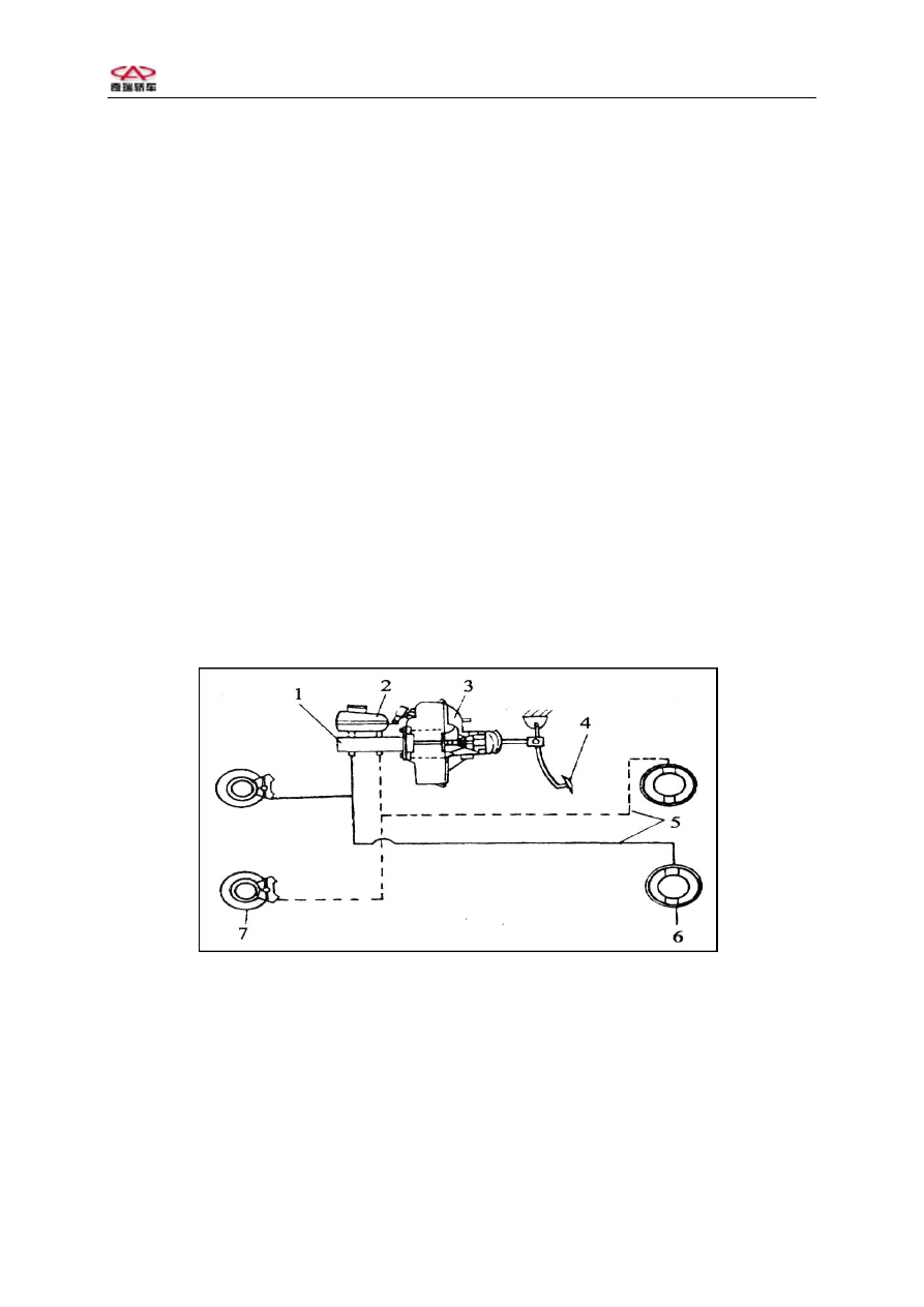
QQ Car Brake System 

1-Brake mast cylinder; 2- Liquid storage tank;3 -Vacuum actuator; 4-Brake 

pedal;5-B raking line;6-Rear wheel drum type brake;7-Front wheel disc type 
brake; 
 

The static status braking control mechanisms are arranged in between the 

front seats, which directly act on the brake arms of the two rear wheels by way 
of the sheathed wires with small friction resistance. The rear wheel brake also  


1


Chery QQ Service Manual                                                                Chassis System 

acts as the static status brake, featuring simple configuration and practicality 
as well as high efficiency in operations. The braking pipeline system of the 
QQ cars adopts the diagonally arrayed dual-loop braking system. The front chamber 
of the main cylinder is connected to the brake of the left front wheel and the 
brake on the right of the rear shaft. The rear chamber of the main cylinder is 
connected to the brakes of the right front wheel and the left rear wheel. Such 
arrangement is based on the idea of simple configuration. In the event that either 
loop fails to perform properly, the remaining braking force will keep up to 50 
% of the normal value. That means no matter which loop fails to work, the basic 
requirements for braking can still be satisfied.  


1、 Front steering knuckle and disk type brake assembly;  2、Braking pawl 
fastening screw;  3、Steering knuckle;  4、Bearing;   5、Dust shield; 6、
Brake disk;  7、Front wheel hub; 8、Jump ring;  9、Fastening screw; 10、
Braking branch pump;   11、Friction block;  


2


Chery QQ Service Manual                                                                Chassis System 


1. Brake base plate; 2. Branch pump; 3. Brake shoe; 4. Upper reset spring of 
brake shoe; 5. Brake spacing self adjustment assembly; 6. Bolt; 7. Lower reset 
spring of brake shoe; 8. Spring; 9. Dust-proof cover; 10. Brake drum locking 
screw nut; 11. Jump ring; 12. Guard ring; 13. Bearing; 14. Brake drum; 15. Rear 
wheel brake assembly; 


3


Chery QQ Service Manual                                                                Chassis System 


1. Parking brake system;2. Bolt; 3. Nut; 4. Lock pin; 5. Parking brake cable; 
7. Axis pin;8..Ap ron;9. Cable rubber sheath 


1. Schematic diagram of brake alarming system


1). Refer to the “Schematic Diagram of Instruments” for the brake liquid sensor 

and static brake switch electric circuitry; 

2). Refer to the Schematic Diagram of Brake Lights for the electric circuitry 

of the brake switch. 


2. Diagnostic information and procedures 

1). Checklist for hydraulic brake diagnostic system 


4


Content   ..  20  21  22  23   ..