Chery S11 / Chery QQ. Manual - part 14
 

  Index      Chery     Chery S11 / Chery QQ - service repair manual


Search            


Content   ..  12  13  14  15   ..


Chery S11 / Chery QQ. Manual - part 14


Chery QQ Service Manual                                            Transmission System


1.Remove the slotted spring pin and disassemble every part. 
2.Clean every part thoroughly and determine if some parts need to be replaced.   
3.Install all the parts according to the figure and the installing order. 

Notice: 

 Division reverse shift fork spring and shift spring. 
 Accurately install the reverse shift fork ball。 
 Install the shift fork Slotted spring pin according to the reverse order. 

 
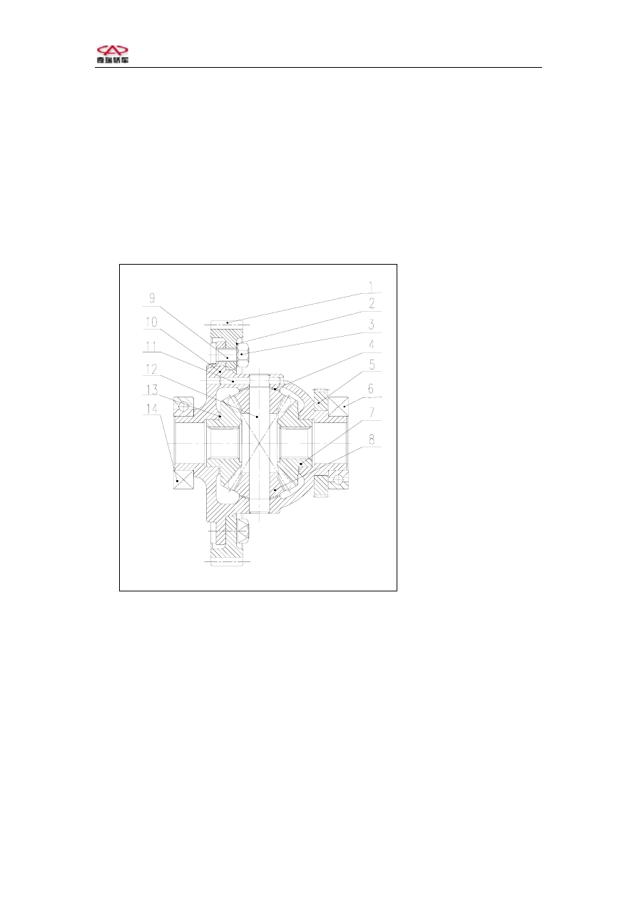
7Differential Assembly   

Disassembling: 
 

1- Differential ring gear     

2-Lock nut    

3- Nut   

4- Pinion gear gasket   

5- Speedometer gear   

6- Bearing   

7- Side gear   

8- Pinion gear   

9- Differential bolt    

10- Differential case   

11-Pinion gear shaft pin 

12-Pinion gear shaft   

13-Side gear gasket 

14-nearside bearing 


            Fig.3-49 Differential assembly  
 
1. Remove the right-side bearing. 
2. Pull out the speedometer gear.   


-77-  


Chery QQ Service Manual                                            Transmission System


1- Bearing puller   

2- Special tool     

3- Bearing   

4-Speedometer gear 


        Fig.3-50 
3. Remove the left-side bearing . 


1- Bearing puller 

2- Special tool    

3-Left bearing   

           Fig.3-51 
 
4. Clip the differential case, remove the 8 nut, 8 Differential bolt and 4 lock nut. 
5. Hammer off the slotted spring pin, remove the pinion gear shaft,pinion gear  ,


side gear. 


1- Differential case   

2- Side gear   

3- Pinion gear shaft   

4- Special tool   

         Fig.3-52 


-78-  


Chery QQ Service Manual                                            Transmission System


Adjustment and Re-installation: 
After disassembling, check if there is any distortion and make a record. Replace 

the attainted parts, clean all the new parts and install.   

1,  Installation side gear,measure the clearance of side gear. Install the side 

gear.  
side gear clearance:0.03~0.40 mm。 
Left Side: 

Clip the differential case, put the end of the dial indicator on the top of the gear. 
Use 2 screwdrivers to move the gear, read the reading on the dial indicator.     


    Fig.3-53 

Right Side: 

According to the same process above, put the end of the dial indicator on the step 

of the side gear.       

-79-  


               Fig.3-54 

2,    If the clearance exceed the regulations, please choose suitable side gear  adjust 
gasket to install once more and test to obtain the right gear clearance. 


mm 

0.70 
0.80 
0.90 
1.00 

Selectable  

  gear adjust gasket   

1.10 

Right 

left 

1- Side gear 

2-Dial indicator


1-Screwdirver 

2- Side gear 

3-Dial indicator


Chery QQ Service Manual                                            Transmission System


Notice: Spread lubricant on the contact surface of side gear adjust gasket,      pinion 
gear,    pinion gear and pinion gear shaft, side gear and differential    case. 

3,    Dive in the slotted spring pin, till the end of pin enter into the differential 

case thoroughly.   

4,    Install the left-side bearing. 
5,    Refer to the fig., install the speedometer driven gear,use special  tool to 

support bearing,drift the lift-side bearing,and then install the right-side bearing 
according to the step 4。   


1-Differential right bearing 

2-Speedometer driven gear 

3-Slotted spring pin 

4-Differential case 

5-Differential left bearing 

6-Special tool 


7-special tool   

          Fig.3-55 
 
6,  Clip the differential case ,install the differential ring driven gear, screw 

tightly the 8 differential    ring driven gear bolt according to the torque, 
Caution: Forbid to use non-professional bolt. 
Torque  :80~100N·m  


1-Driven gear bolt 

2-Differential ring

driven gear 

3-Torque spanner 


             Fig.3-56 


-80-  


Content   ..  12  13  14  15   ..