Chery S11 / Chery QQ. Manual - part 13
 

  Index      Chery     Chery S11 / Chery QQ - service repair manual


Search            


Content   ..  11  12  13  14   ..


Chery S11 / Chery QQ. Manual - part 13


Chery QQ Service Manual                                            Transmission System


1-3rd, 4th spacer   

2-3rd driven gear   

3- 2nd driven gear   

4- Special tool   

5- Special tool   

        Fig.3-42 
 
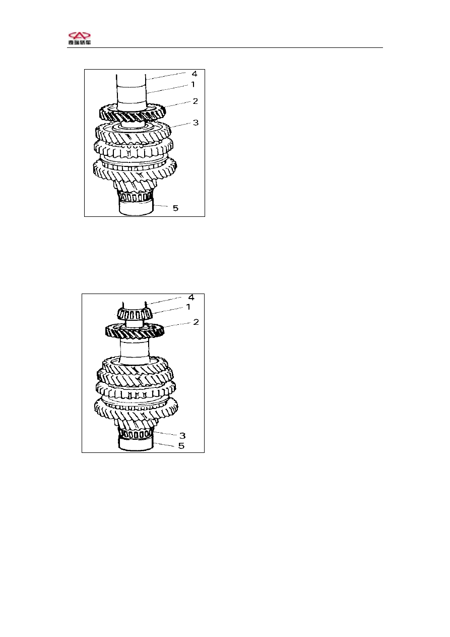
10. Use the same special tools to install the 4th driven gear. 
11. Use hammer or special tools to install the left bearing.   

Notice: To protect the bearing, use the special tools (shown in the figure) to support 
the bearing.   


1- Left bearing   

2-4th driven gear   

3-Right bearing   

4- Special tool   

5- Special tool   

      Fig.3-43 

 
6  Shift and  select  lever  shaft  control system  

Shift and select lever shaft assembly: 


-73-  


Chery QQ Service Manual                                            Transmission System


F

Fig.3-44 Shift and select lever shaft assembly 

1-   Shift and select lever shaft    2- Gasket     3- Slotted spring pin  
4-  Select    lever    shaft                    5-  Slotted    spring    pin                  6-  Spring                       
7-  Shift    cam    spring                8-  Shift    cam                9-  Slotted    spring    pin               
10- Return   spring   11- Interlock  12- Slotted spring pin      
13- Return spring       14-E- snap ring  


1.Use the professional tools to remove the 4 pin, 3 E- snap ring and component 

from the select lever shaft.     

2. Clear up all the parts, if necessary, please replace the used parts. 
3. Install according to the reverse process. 

Notice: 

   When hammering the slotted spring pin, use the wood block to support to 

prevent bending the shift and select lever shaft.   

   When installing reverse, 5th interlock roller, first enlace the cam      return 

spring, secondly hammer the slotted spring pin.   

   Keep the identical directions of the select lever shaft, reverse, 5th shift cam 

and spring. 

1st, 2nd shift fork shaft assembly and 3rd, 4th Shift fork shaft assembly. 


-74-  


Chery QQ Service Manual                                            Transmission System


1-1st.2nd Shift fork   shaft 

2-1st .2nd Shift head 

3-1st .2nd Shift fork     

 1st , 2nd  Shift  fork    shaft  assembly 


1-3rd, 4th Shift fork shaft   

2-3rd, 4th Shift head   

3-3rd, 4th Shift fork   


3rd, 4th Shift fork shaft assembly. 
 
1.Use the professional tools to remove the 3 pin and component (from the select   

lever  shaft assembly. 

2.Clean up all the parts, if necessary, please replace the used parts. 
3.Install according to the reverse process of disassembly. 

Notice: When installing, Shift fork Slotted spring pin placket should stagger 180  º. 
Check Shift fork and shift hub sleeve. 


-75-  


Chery QQ Service Manual                                            Transmission System


1- Shift fork     

2- Hub sleeve   

             Fig.3-47 
1.Use feeler gauge to check the clearance between shift fork and hub sleeve, if 

the clearance exceeds 1.0mm, please replace the parts.     
Notice: Check the contact position of shift fork and hub sleeve carefully to determine 
if replace the parts. 
Clearance“a”  :  Maintenance Limit: 1.0mm 

2. Insert the shift lever into the hole of the case, check if it works smoothly, if 

there is any retardarce, please correct with winch or similar tools.     

Reverse, 5th shift fork shaft assembly   


1- Reverse Shift fork     

2- Spring   

3- Ball   

4- Slotted spring pin     

5-Reverse, 5th  Shift  fork  

6-Reverse , 5th  Shift  head 

7-Reverse , 5th    guide shaft 

A :

Slotted spring pin

placket  forward   

          Fig.3-48 


-76-  


Content   ..  11  12  13  14   ..