Chery Fora (Elara A520). Manual - part 167
 

  Index      Chery     Chery Fora (Elara A520) - service repair manual


Search            


Content   ..  165  166  167  168   ..


Chery Fora (Elara A520). Manual - part 167


CHERY A21 SERVICE MANUAL


MECHANISM OF 2.0NALC ENGINE 

41 


6.2


Installation 

1) 

Clean the oil seal seat ring. Clean the oil 
seal seat ring with clean oiled gauze.


2) 

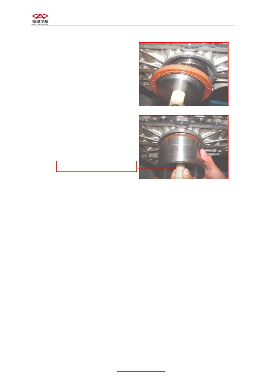
Spread  the  oil  at  the  lip  of  crankshaft 
front oil seal. 

Enclose  the 

guide  sleeve  of  crankshaft  oil 

seal

,  special  tool,  with  that  oil  seal.  Then 

press it into oil seal seat ring. 


3) 

Mount  the  flywheel  and  the  clutch 
pressure  plate,  and  then  mount  the 
engine on the vehicle. 

Torque:25±5N.M, then screw 30°±5°. 

7. Replace crankshaft and thrust washer 

7.1  Needed tools and auxiliary materials 

A  set  of  open  end  wrenches,  a  set  of  sleeve 
tools,  a  small  hoist,  Le  Tai  glue,  Engine  oil, 
feeler gauge, feeler gauge, micrometer gauge. 

7.2  Process of Removal 

1) 

Suspend  the  engine  assembly  from 
vehicle  (See  “suspending  of  engine 
assembly” for details). 

2) 

Drain out the engine oil. 

3) 

Remove  the  timing  belt  (see  “replace 
timing belt” for details). 


Guide Sleeve of Crankshaft Oil Seal


CHERY A21 SERVICE MANUAL


MECHANISM OF 2.0NALC ENGINE 

42 


4)


Dismantle  the  accessories,  such  as 
dynamo, 

A/C 

compressor, 

power 

steering  pump  and  bracket. ( See  the 
“replacement  of  engine  accessory”  for 
details) 

5) 

Dismantle  the  engine  cylinder  head 
assembly. ( See  the  “replacement  of 
cylinder head” for details) 

6) 

Dismantle  the  engine  clutch  pressure 
plate,  the  flywheel  and  the  timing  belt 
pulley. 

7) 

Remove  the  oil  pan  and  engine  oil 
strainer.(See the “replacement of oil pan 
and strainer” for details.) 

8) 

Remove  the  piston  connecting  rod 
assemblies  for 4 cylinders and Put them 
in order. 

Note:  You’d  better  stick  the  number  on  each 
piston  connecting  rod  assembly  to  prevent 
from wrong mounting. 

9) 

Dismantle engine oil pump assembly. 

10)  Dismantle  the  frame  assembly  under 

cylinder 

block 

and 

remove 

the 

crankshaft and thrust washer.


7.3  Inspection 

1) 

radial clearance of crankshaft 

a):  Clean the journal and bearing bushing. 

b):  Install crankshaft 

c):  Make  the  length  of  plastic  clearance 

gauge  equal  to  the  width  of  bearing. 
Then put it on the journal paralleling the 
axis. 


Clearance Gauge 

CHERY A21 SERVICE MANUAL


MECHANISM OF 2.0NALC ENGINE 

43 


d):


Mount  the  main  bearing  cap  carefully 
and  screw  down  the  bolt  with 
specified torque. 


e):


Dismantle 

the 

main 

bearing 

cap 

carefully. 

f):


Measure  the  width  at  the  most  bread 
part of pressed plastic  line with ruler on 
plastic  clearance  gauge  package,  then 
get clearance value. 


Standard Value 

Clearance 

-0.0035-0.034 

Replace  the  new  bearing  bushing  if  the 
measured  clearance  value  exceeds  the  limit 
value. 

Note:  Replace  the  whole  group  when 
replacing bearing bushing.


Selecting method of main bearing bushing: 

By  observing  the  sign  on  cylinder  (see  the 
picture), we could see 5 As which correspond 
to bearing bushings respectively. 

There  two  kinds  of  signs  on  this  vehicle,  A 
and  B,  corresponding  to  two  kinds  bushing, 
red  one  and  blue  one  (the  color  can  be 
recognized  on  the  new  bushing  but  it  is 
possible  unrecognized  the  color  on  the  old 
one.)  A  corresponds  to  red  bushing,  and  B 
corresponds to blue bushing. 


CHERY A21 SERVICE MANUAL


MECHANISM OF 2.0NALC ENGINE 

44 


2)


Inspect the crankshaft axial clearance 

Mount the crankshaft and  measure  its radical 
clearance with micrometer guage.


Standard Value 

Clearance 

0.076—0.265 

Replace  the  new  thrust  washer  if  the 
measured value exceeds the limit value. 

Standard thickness of thrust washer: 


7.4


Installation 

1)


Clean  the  engine  and  spread  the  engine 
transmission  oil  on  the  crankshaft 
journal. 

2)


Mount the crankshaft correctly and then 
mount the thrust washer. 


3)


Mount  the  cylinder  frame  and  screw 
down the crankshaft fastening bolt. 

See the picture for the screwing sequence 

Screwing way and Torque: 

A:


Pre-fasten  the  bolt  according  to  the 
sequence in the picture. 

B:


Screw  the  bolt  as  the  sequence  on  the 
picture to 45±5 N.m. 

C:


Screw 180±5° 

4)


Mount  and  screw  down  the  bolt  of 
frame periphery. 

Torque: 23N.m 

5) 

Mount  the  engine  oil  strainer,  oil  pan, 
crankshaft front and rear oil seal and oil 
pump. 

6) 

Mount  the  engine  accessories,  suspend 
the  engine  assembly  from  vehicle  and 


Content   ..  165  166  167  168   ..