Chery Fora (Elara A520). Manual - part 165
 

  Index      Chery     Chery Fora (Elara A520) - service repair manual


Search            


Content   ..  163  164  165  166   ..


Chery Fora (Elara A520). Manual - part 165


CHERY A21 SERVICE MANUAL


MECHANISM OF 2.0NALC ENGINE 

33 


4)


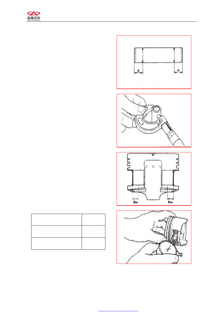
Inspect  the  diameter  of  piston  pin  and 
piston pin hole. 

a. 

As  the  following  picture,  measure  the 
piston 

pin 

position 

around 

with 

micrometer  caliper.  And  take  the 
maximum  value  as  the  diameter  of 
piston pin.


b. 

Measure the diameter of piston pin  hole 
around  with  micrometer  guage  for 
inside diameter, as the following picture, 
and  take  the  minimum  value  as  the 
diameter of pin hole. 


Replace  with  the  new  piston  and  pin  if  the 
examined clearance exceeds the limit. 


Standard 

Size 

Diameter of piston pin 

21

0

005

.

0


Diameter of piston pin 

hole 

21

008

.

0

002

.

0


CHERY A21 SERVICE MANUAL


MECHANISM OF 2.0NALC ENGINE 

34 


5)


Inspect  the  connecting  rod  journal  and 
connecting rod bearing 

a.


Examine the diameter of connecting rod 
journal. 

Measure  the  axle  diameter of  connecting  rod 
with micrometer caliper. 


Rotate  the  crankshaft  90°  and  measure  it 
again. 

Work  out  the  Roundness  and  cylindricity 
through twice measuring. 


Roundness=Max.  diameter  —   Min. 
diameter  /2  as  the  picture,  take  the 
vertical  diameters  on  the  same  plane, 
subtract  the  half  of  Minimum  from  the 
Maximum to get roundness. 


cylindricity= 

Maximum 

bore

Minimum  bore/2  As  the  picture, 
measure  the  bores  of  3  planes  along 
both  A  direction  and  B  direction 
respectively.  Get  the  maximum  and  the 
minimum  from  6  values,  and  then 
subtract  the  half  of  Minimum  from  the 
Maximum to get cylindricity; 


b.


Inspect 

the 

radial 

clearance 

of 

connecting rod bearing   

Inspect the radial clearance of connecting rod 
bearing  with  clearance  gauge.  Clean  up  the 
connecting  rod  journal  and  connecting  rod 
bearing.  And  put  clearance  gauge  on  the 
journal, fasten bearing bushing and fasten the 
bolt according to set torque. 

Note: Do not rotate the crankshaft during the 
process. 


Standard Value 

Diameter 

9

.

47

0

016

.

0


Roundness 

—— 

Cylindricity 

—— 


CHERY A21 SERVICE MANUAL


MECHANISM OF 2.0NALC ENGINE 

35 


Loosen  the  connecting  rod  bolt,  remove  the 
cap,  and  measure  the  maximum  width  of 
pressed clearance  gauge  with  the  ruler  on  its 
package to get the clearance value. 

Replace with the new connecting rod bearing 
if the examined clearance exceeds the limit. 

Note:  Use  the  same  brand  consistent  with 
assorting  sign  when  you  replace  the  bearing 
bushing.


Standard 

Value 

Abrasion 

Limit 

Clearance  0.016—0.051 


Selection of connecting rod bearing: 

You may select the connecting rod bearing by 
observing the sign on the first balance weight 
at  the  front  end  of  crankshaft.

(see  picture, 

unavailable)


6)


Inspect  the  planeness  of  cylinder  block 
surface. 

a:


Clean  the  upper  surface  of  cylinder 
block. 

b:


Check  with  ruler  and  feeler  gauge 
whether  the  surface  of  cylinder  block  is 
warped.  (Measure  it  in  the  sequence  of 
A, C, D, E, F, G in the picture) 

C:


Revise  it  if  the  warping  amount  is 
excessive. 

Replace  with  the  new  cylinder  if  it  exceeds 
the  limit.  The  maximum  for  the  sum  of 
permitted  abrading  thickness  of  cylinder 
block and cylinder head is: 


Standard Value 

limit 

value 

warping 

amount 

0.04 


Clearance Gauge  of Plastic 


CHERY A21 SERVICE MANUAL


MECHANISM OF 2.0NALC ENGINE 

36 


7) 

Inspect cylinder 

a: 

Inspect  if  the  cylinder  wall  is  scratched 
or  scored.

  If  there  are  cylinder  scoring 

and scratching you need to hone cylinder 
wall,  replace  cylinder  liner  or  replace 
cylinder block.


b: 

Examine 

the 

inner 

diameter 

and 

cylindricity  of  cylinder  with  cylinder 
gauge. 


Standard value 

Inner diameter 

83.5 

cylindricity 

0.008 

cylindricity=  Maximum  bore - Minimum 
bore/2 

As  the  picture,  measure  the  bores  of  3  planes 
along  both  A  direction  and  B  direction 
respectively.  Get  the  maximum  and  the 
minimum from 6 values, and then subtract the 
half  of  Minimum  from  the  Maximum  to  get 
cylindricity;


3.2.3  Installation 

1) 

Spread  oil  on  the  piston  pin  and  in  the 
piston  pin  hole,  connect  the  piston  and 
connecting  rod  with  piston  pin,  and 
mount the piston pin circlip. 


2) 

Mount  the  piston  ring.  Mount  the  rings 
on  the  piston  in  the  sequence  of  oil  ring 
expander, upper and lower segments, 2nd 
air ring  and  1st  air  ring;  Pay  attention to 
the direction of piston ring, the side with 

TOP

”  should  be  upward.  The  two 

segments  and  expander  are  staggered. 
The  angle  of  expander  connector  points 
to the top of piston, and the 1st ring and 
2nd  ring  form 

120°

  with  the  upper 

expander. 


12 mm 

Center 

Bottom 


The Openings Of Rings Form 

120°With Each Other.


Content   ..  163  164  165  166   ..