Chery Fora (Elara A520). Manual - part 111
CHERY A520 SERVICE MANUAL CHASSIS
20
they are damaged.
11) After repairing the brake hydraulic system or finding the brake pedal is becoming soft
during operation, you should discharge the air from the brake system in accordance with
required method and sequence.
12) You should try your best to select the tires recommended by the automobile
manufacturers. If the using of tires in other types is necessary, you should select the tires
with the outside diameter, traction performance and rotary inertia similar to the former
ones, but should not select the tires with different specifications, which shall impose
influence on the control effects of ABS.
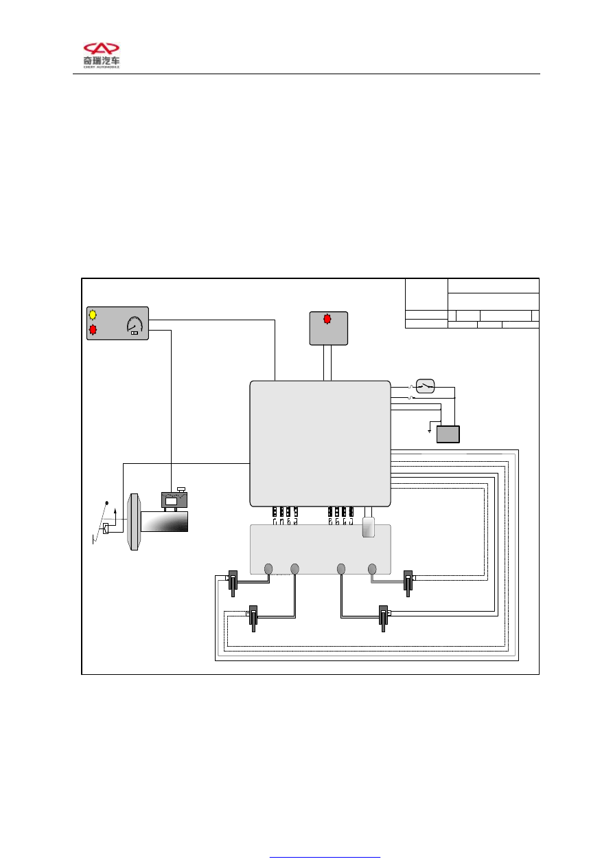
8.2 Schematic diagram of abs control
This is the property of and contains confidential and proprietary information of TRW Inc. and is diclosed subject to the terms of a confidentialiry/secrecy agreement between your company and TRW. This is not to be transmitted, reproduced, used or disclos
manner contrary to the terms of the agreement.
HCU 440V
A
BS
M
o
tor
L
F I
so
L
F
D
u
mp
R
F I
so
R
F
D
u
mp
ABS Warning Lamp
(Discrete)
Master
Cylinder
Brake
Fluid
Reservoir
IGN+
Brake
Pedal
Brake
Switch
LF
LR
RF
Wheelspee
d
Sensor
Wheelspeed
Sensor
Brake
Booster
INSTRUMENT CLUSTER
Brake Warning
Lamp
ABS Warning
Lamp
LF Wheelspeed +
LF Wheelspeed -
L
F I
so
L
F
D
u
mp
EBC440V ABS
A
B
S
P
u
m
p
+
A
B
S
P
u
mp
-
L
R
I
so
L
R
D
u
mp
R
R
I
so
R
R
D
u
mp
R
F
I
so
R
F
D
u
mp
L
R
I
so
L
R
D
u
mp
RR
I
so
R
R
D
u
mp
LR Wheelspeed +
LR Wheelspeed -
RR Wheelspeed +
RR Wheelspeed -
RF Wheelspeed +
RF Wheelspeed -
RR
Wheelspeed
Sensor
Chery S11 EBC440V System Schematic
ABS Only System
SIZE
FSCM NO
DWG NO
REV
B
A
SCALE
1 : 1
SHEET
1
Brake Switch
Ignition
Switch
ABS Motor B+
ABS Motor Gnd
ECU Gnd
ECU
Supply
Battery
+
-
Speedometer
Odometer
LF
RR
LR
RF
Wheelspeed
Sensor
C
A
N
_H
A
na
log
/D
is
cr
e
te
Keyword2000
Diagnostics
C
A
N
_L