Chery Fora (Elara A520). Manual - part 7
 

  Index      Chery     Chery Fora (Elara A520) - service repair manual


Search            


Content   ..  5  6  7  8   ..


Chery Fora (Elara A520). Manual - part 7


Chery Service Manual for A520                    Body Dimension and Accessories


bolts  of  the  front  row  seats  seat  belts  and 
make  sure  that  the  latch  of  the  seat  belts 
could  be  operated  easily  and  the  tightening 
torque  for  the  fixing  nuts  is  50±5  N•m. 
(uniform  thread  fastening  glue  should  be 
applied  to  all  fasteners  of  this  assembly 
before  installing)  The  belts  could  extend  and 
shrink  easily  and  could  not  slack  after  the 
latch  is  fastened  with  the  lock  striker.  The 
installation  angle  of  the  left/right  rear  seat 
belt retractor assembly  is 90°. The tightening 
torque  for  all  fasteners  of  this  assembly  is 
50±5N•m and the fasteners should be applied 
with  the  thread  fastening  glue  before 
installing.  The  belts  could  extend  and  shrink 
easily  and  could  not  slack  after  the  latch  is 
fastened with the lock striker. The catch bolts 
of the middle seat belt should be applied with 
thread  fastening  glue  and  the  tightening 
torque of which is 50±5N•m. The lock screw 
of the double end clip ring should  be applied 
with thread  fastening  glue  and  the  tightening 
torque of which is 50±10N•m;


Figure 99 


Figure 100 

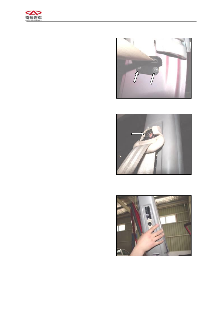
7.


Remove  the  upper  trim  panel  for  B 
pillar;


Figure 101


Chery Service Manual for A520                    Body Dimension and Accessories


8.


Remove the two bolts and slider track;


Figure 102


9.


Remove the weather strip;


Figure 103


10.


The  inner  harness  connector  on  the  left 
rear door as shown;


Figure 104


Chery Service Manual for A520                    Body Dimension and Accessories


11.


From  here  outwards  to  pull  out  the 
harness;


Figure 105


12.


Remove C pillar trim panel;


Figure 106


13.


Remove  the  weather  strip  from  the  left 
rear door;


Figure 107


Chery Service Manual for A520                    Body Dimension and Accessories


14.


Disassembling 

the 

passenger 

grab 

handle:  lift  the  trim  cover  and  unscrew 
the two set screws to detach the handle:


Figure 108


15.


Disassembling  the  sun  visor:  unscrew 
the fastening bolts; 

Assembly  requirement:  The  tightening  force 
for the screw should be proper and make sure 
that  the  sun  visor  could  work  normally 
without  any  looseness.  The  sun  visor  could 
move  freely  when  working  normally  without 
any noise and being stuck.


Figure 109


16.


Remove the fixing base; 

Assembly requirement: The fixing base could 
seize  the  sun  visor  properly  so  as  to  prevent 
the sun visor from breaking away when being 
used.


Figure 110


Content   ..  5  6  7  8   ..