Chery B11. Manual - part 192


  Index      Chery     Chery B11 - service repair manual


Search            


Content   ..  190  191  192  193   ..


Chery B11. Manual - part 192


Chery B11 Service Manual                                                                  Four-wheel alignment


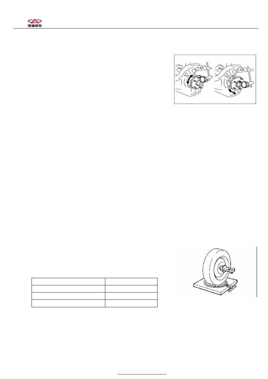
III. Check loosening degree of wheel bearing   

1、Check bearing axial clearance   

  Maximum: 0.05mm 

2、Check deflection of axle rim 

Maximum: 0.05mm 


IV. 

Check loosening degree of front suspension 

V. 

Check loosening degree of steering horizontal linkage 

VI. 

Check loosening degree of knuckle joint end 

VII. 

Check if shock absorber can operate properly.   

1、Check if there’s oil leakage. 

2、Check if there’s abrasion of assembly liner. 

3、Check damping force of shock absorber. If it’s disqualification, it’s needed to be replaced. 


Section 2 Rear Wheel Alignment 

It’s  commended  for  the  chassis  of  this  vehicle  type  to  use  four-wheel  position  indicator  by  propulsive  line  positioning 

methods. Single wheel toe-in of front wheel shall be influenced, if propulsive line positioning adjust rear wheel toe-in .So 

if carrying out four-wheel alignment test, adjust rear wheel first, then adjust front wheel. And adjust camber of rear wheel 

first, then toe-in angle. After that, adjust caster, camber and toe-in angle of front wheel. 

  I. 

Install position indicator or retainer in wheels. 

1、Install it according specific instruction of equipment manufacturer. 

2、Test  and  adjust  vehicles  according  to  equipment  requirement,  see  the 

following alignment requirements:


Total toe of rear wheels 

18

1

±12

1


Single wheel toe-in of rear wheels 

9

1

±6

1


Camber of rear wheels 

-35

1

±60

1


Thrust angle 

-10

1

~+15


Note:  Camber  of  rear  wheels  isn’t  adjustable.  If  finding  abnormal  tyre  abrasion  of  rear  wheels  ,  check  if  there’s 

abrasion and 

deformation in rear suspension.


PDF created with pdfFactory Pro trial version 

www.pdffactory.com

Chery B11 Service Manual                                                                  Four-wheel alignment


II. 

Adjust rear wheel toe-in 

If  rear  wheel  toe-in  can’t  conform  to  requirements,  adjust  it.  It’s 

allowable  to  adjust  offset  bolt  16  of  rear  suspension  swinging  arm 

assembly  and  change  toe-in  size  (The  detailed  adjustment  procedures 

are as follows). 

1、  Loosen  Nut  18,  pay  attention  not  to  making  nuts  drop  from 

the groove. 

2、Rotate  offset  bolt  16  to  change  rear  wheel  toe-in  value  till 

conforming to requirements. 

3、Screw Nut18 on to assigned moment of a force 

4、After screwing nuts on, bounce vehicle body to check toe-in size.


16 

18 

PDF created with pdfFactory Pro trial version 

www.pdffactory.com

Chery B11 Service Manual                                                                  Four-wheel alignment


Section 3 Front Wheel Alignment 


I. Install position indicator or retainer in wheels. 

Install it according to specific instruction of equipment manufacturer. 

II.  Test  and  adjust  negative  caster,  camber,  toe-in  angle  of  front 

wheels and steering angle 

Specification:  follow  the  requirements  of  vehicle  front  wheel 

alignment: 

Negative caster 

3°.13

1

±60

1


Camber  of  front 

wheels 

-30

1

±60

1


Single 

wheel 

toe-in  of  front 

wheels 

1

1

±4

1


Steering angle 

Inner: 

39.9

0

±4°             

Outer:33.5

0

±4 

Note: First adjust caster, next camber, then toe-in angle. 

1、

Negative Caster 

Negative caster is assured in design structure. There’s no need to adjust it. 


Influence of Caster 

Main function of caster is to make vehicles run in the direction of straight front. 

If caster is in the right position, the inner of vehicles shall go down when turning front wheels. Its result is to hoist 

the  chassis  and  add  load  to  steering  knuckle.  If  two  front  wheels  have  the  same  caster,  vehicles  will  turn  back  to  the 

direction  of  straight  front  after  turning.  To  add  positive  caster  angle  can  increase  stability  of  steering  wheel,  but  it’ll 

increase  turning  force  when  turning.  To  reduce  positive  caster  angle  can  decrease  stability  of  steering  wheel,  but  it’ll 

decrease turning force when turning. The angle of caster won’t influence abrasion of tyres. It’s used to stabilize vehicle 

running  direction  and  make  steering  wheel  turn  back  by  itself  when  turning.  If  vehicle  equipments  are  tradition 

mechanical turning, the angle of caster is small, without so much as tending to minus caster angle, and it’s easy to turn. 

If  vehicles are equipped  with power-steering, caster is regulated to bigger positive caster and it can  make  drivers  have 

more feelings of driving .To add positive caster angle can increase turning force, but it’ll increase stability when running 

in the straight direction. 


PDF created with pdfFactory Pro trial version 

www.pdffactory.com

Chery B11 Service Manual                                                                  Four-wheel alignment


2、

Camber 

After  installing  independent  suspension  and  steering 

knuckle,  there’s  no  need  to  adjust  camber  normally.  If 

finding  camber  deviate  tolerance  for  other  reasons,  use 

binding  bolts  of  independent  suspension  and  steering 

knuckle to calibrate. 

(1)  Before  revising,  sight  check  if  there’s  damage  in 

running 

system 

components. 

Replace 

components 

damaged.  Camber  of  front  wheels  designed  by  the 

manufacturer isn’t adjustable. 

(2) 

If finding

 camber of front wheels exceeds deviation, loosen binding bolts of front shock absorber and steering 

knuckle and calibrate it by moving wheels. 


3、Front Wheel Toe-in


Use special four-wheel position indicator to test and adjust toe-in. 

(1) According to requirements of position indicator, locate wheels to prepare for alignment. Fasten steering wheel in 

the direction of straight front with limiting device of 

steering wheel, which can be bought in the 

market.( Steering wheel must be in the center position of ±5° and lower flange clamping bolt of steering shaft must be 

level.) 
 

(2) Loosen the lock nut (1) of steering horizontal linkage. 

(3) Dismantle flexible sheath retaining ring (2) with pinchers. 

Caution: If retaining ring is lack of elasticity, 

It is needed to replace it. 

(4)  According  to  requirements,  screw  toe-in  adjusting  rod  to 

adjust the length to assigned value. 

(5)  Screw  lock  nut  (1)  on  and  install  flexible  sheath  retaining  ring  (2)  again.  Check  if  screwing  nuts  on  and  the 

sheath is in the right position. 

(6) After adjusting front wheel toe-in, check if steering wheel is level. .If not, loosen lock nut of steering wheel and 

adjust  steering  wheel  to  level  position  .And  screw  lock  nut  of  steering  wheel  on  and  adjust  steering  wheel  to 

requirements of the moment of a force(27~33Nm). 

4、

Check Front Wheel Steering Angle 

After  replacing  horizontal  linkage  tie-in  or  adjusting  toe-in,  check  steering  angle.  If  front  wheel  steering  angle  can’t 

conform to the standard, check and adjust the length of left and right horizontal linkages. 


Bolts 

adjustment 

(1) 

(2) 

PDF created with pdfFactory Pro trial version 

www.pdffactory.com


Content   ..  190  191  192  193   ..