Chery B11. Manual - part 121


  Index      Chery     Chery B11 - service repair manual


Search            


Content   ..  119  120  121  122   ..


Chery B11. Manual - part 121


Chery B11 Service Manual


Air Conditioner-7 


Section 4 Windshield Location 


3.0.9: CHERY AUTO CASE/AIR PIPE SYSTEM 

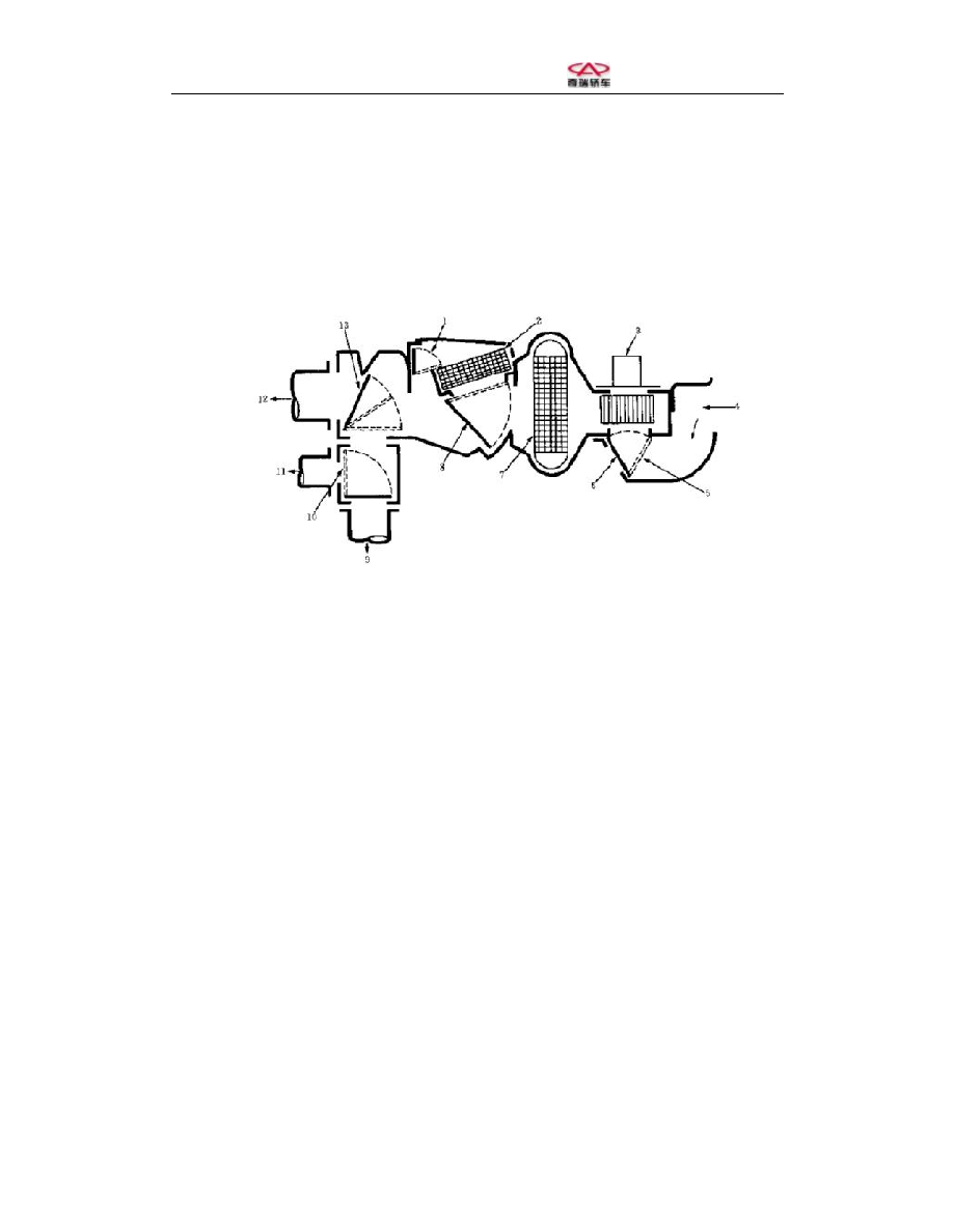
The separate type casing system with a blower 

1—Choke    2—Heater core    3—Blower motor    4—Fresh air   

5—Fresh/Recirculation air damper    6—Recirculation air    7—Evaporator core   

8—Mixed air damper      9—To panel    10—A/C defroster damper    11—To 

defroster    12—To the bottom outlet    13—Heater defroster damper 


Chery B11 Service Manual


Air Conditioner-8 

Section 5 Particulars for Tools and Equipment 

Air conditioner maintenance kit   


Service valve for draining refrigerant 


Refrigerant charging gauge 


Refrigerant charging hose 


Green 

Refrigerant charging hose 


Blue 

Refrigerant charging hose 


Orange yellow 

Stop valve 


Complete charging hose kit with stop valve 


If  a  stop valve is required, please 

order this kit. 

Magnetic clutch remover 


Magnetic clutch retainer 


Clasp forceps 


Clasp forceps 


Lip sealing protection 


Chery B11 Service Manual


Air Conditioner-9 

Section 6 Manifold Pressure Gauge Operation Guide 

The  manifold  pressure  gauge  is  a  most  popular  tool 

available  for  the  maintenance  of  A/C  unit,  shown  in  the 

right  figure.  The  low-pressure  gauge  is  not  only  used  to 

indicate the pressure, but to indicate the degree of vacuum 

with  the  reading  range  of  0  to  5x10

5

Pa  (0-760mmHg), 

the pressure scale of which starts from 0 and its range is no 

less  than  4.2X10

5

Pa  (approx.  4.2kgf/cm

2

).  The  pressure 

scale  of  high-pressure  gauge starts  from 0  and  its range  is 

no  less  than  21.1X10

5

Pa  (approx.  21.1  kgf/cm

2

).  These 

two  pressure  gauges  are  installed  on  a  gauge  stand.  Both 

ends  of  gauge  stand  are  respectively  equipped  with  one 

manual  valve, and there are three channel interfaces in the 

bottom of the gauge stand. 

Manifold Pressure Gauge 

1 - Low-pressure gauge (blue).   

2 - High-pressure gauge (red).   

3 - High-pressure side hose (red). 

4 - Hose for maintenance (yellow). 

5 - High-pressure side hose (blue). 

The  interface  of  low-pressure  gauge  connects  to  the  low-pressure  pipe  joint  via  a  hose  while  the 

interface  of  high-pressure  gauge  connects  to  the  high-pressure  pipe  joint  via  a  hose.  The  middle 

interface  connects  to  the  vacuum  pump  or  refrigerant  tank  via  a  hose.  With  the  help  of  the 

combination  action  of  two  manual  valves  and  three  hoses,  the  manifold  pressure  gauge  has  four 

functions (shown in the table below). 


Function of Manifold Pressure Gauge 

Location of High- and Low-pressure Valves 

Functions 

High- and low-pressure valves close simultaneously 

Refrigeration system failure diagnosis 

Low-pressure  valve  open,  and  high-pressure  valve 

close 

Refrigeration system is charged with refrigerant 

or refrigerating machine oil 

Low-pressure  valve  close,  and  high-pressure  valve 

open 

Refrigeration  system  leakage  check  and  quick 

refrigerant charging 

High- and low-pressure valves open simultaneously 

Refrigeration system vacuum pumping 

Note:  The  high-  and  low-pressure  valves  open  means  that  the  high-  and  low-pressure  valves 

connect to the refrigeration system and intermediate pipe respectively. The high- and low-pressure 

valves close means that the high- and low-pressure valves do not connect to the intermediate pipe 

but connect to the refrigeration system respectively. 


Chery B11 Service Manual


Air Conditioner-10 

Section 7 Refrigerant Recycling Equipment Operation Guide 

Recycle 

the 

refrigerant 

from 

the 

refrigeration device 

When  the  refrigerant  is  removed  from  the 

refrigeration device under the following conditions, 

a  recycling  receiver  shall  be  applied  to  recycle  the 

refrigerant.   

Before  the  components  on  the  refrigerant  pipe  are 

replaced. 

When  moisture  or  air  enters  into  the  refrigerant 

pipe. 

When  excessive  refrigerants  are  charged  into  the 

system. 

WARNING: 
●  When  the  recycling  receiver  is  required,  take 

care to operate it according to the requirements 

of device manufacturer's instructions. 


●  After  the  completion  of  recycling  work, 

measure  the  level  of  compressor  oil  recycled 

so  that  the  same  quantity  of  oils  are  added  to 

the refrigeration device in the future. 


Operation guide for refrigerant recycling receiver 

1. 

Install the manifold pressure gauge kit on the service valve. 

2. 

Recycle the refrigerant from the refrigeration device. 

(a)  Connect the intermediate hose to the recycling receiver. 

(b)  Operate the recycling receiver. 

(c)  Open the manual high- and low-pressure valves on the refrigeration pressure gauge kit. 

1. 

After the completion of recycling work, turn off the recycling receiver. 

2. 

Remove the manifold pressure gauge kit from the service valve.

LOW-PRESSURE 

SEVICE VALVE 

RECYCLING 

RECEIVER 

HIGH-PRESSURE 

SEVICE VALVE 

REFRIGERATION DEVICE 

OIL BOTTLE 

DRAINED 
OIL 
QUANTITY 


Content   ..  119  120  121  122   ..