Chery B11. Manual - part 77


  Index      Chery     Chery B11 - service repair manual


Search            


Content   ..  75  76  77  78   ..


Chery B11. Manual - part 77


Chery Automobile Maintenance Manual


29 


V. Spark plug 


check and clean of spark plug 

1、 

Disconnect spark plug cable. 

Caution:When pulling the spark plug 

cable from the spark plug,remember to 

pull it with hand holding the cable cover 

instead of cable itself. 

2、Disassemble spark plug. 

3、Check whether there is any burned electrode 

or damaged insulator.Check whether the 

burning trace is well-distributed. 

4、Clean the carbon accumulation with steel 

brush or special spark plug cleaning tool. 

Blow off grits from the rippling part of spark 

plug with compressed air. 

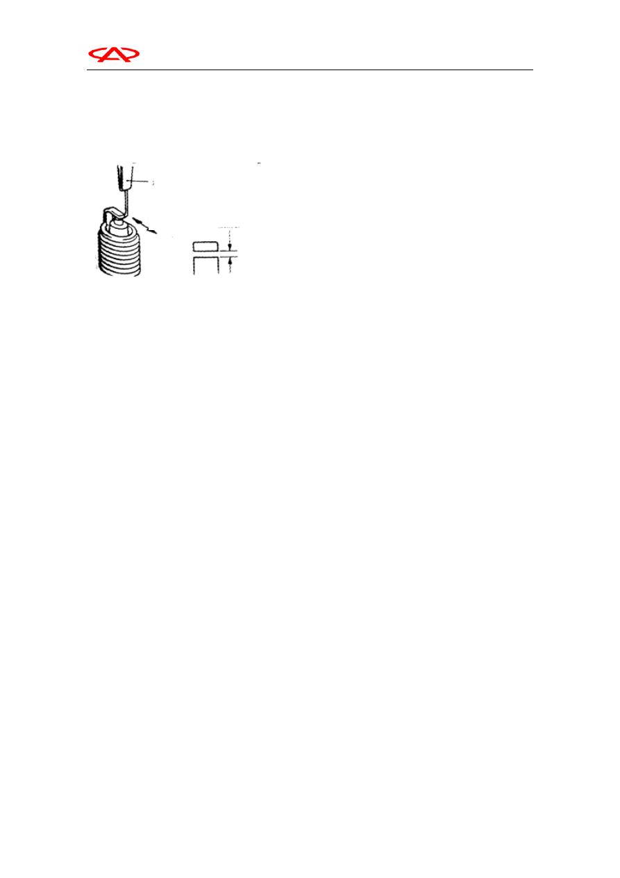
5、Check whether the spark plug clearance is in 

the range of standard value with spark plug 

clearance gauge. 

Standard value: 1.1mm. 

If the spark plug clearance is not within the 

range of standard, bend ground eletrode to 

adjust. 

6、Clean the spark plug hole of engine. 

Caution: Note not to have dirty things 

outside enter the cylinder. 

7、Install spark plug. 


Filler gauge for spark
plug clearance 

Measuring 
direction 

Chery Automobile Maintenance Manual


30 


VI. Knock sensor 

Knock sensor is a sensor testing cylinder 

vibration frequency, which is constituted by  

vibration board and piezoelectric component.


The vibration times of knocking cylinder varies 

with different engines. The vibration board of 

knock sensor vibrates with the vibration of 

cylinder block, while the output voltage of 

piezoelectric component varies with the change 

of vibration frequency of vibration board. 

When the knock occurs, the vibration board 

vibrates with the vibration of cylinder in a 

higher degree, while the piezoelectric 

component generates higher voltage. When the 

knock stops, the piezoelectric component 

generates lower voltage. 


The relationship between output voltage of 

piezoelectric component and vibration 

frequency is showed as the left illustration. 


The advance angle of ignition set value in the 

engine with knock sensor is bigger and the 

power is higher; while in the engine without 

knock sensor, the set value of advance angle of 

ignition is comparatively more conservative, 

and so is the power.   


Resonance 

point 

Vibration frequency 


Knock sensor output voltage 

O

u

tput voltage


Chery Automobile Maintenance Manual

33

Chapter 4 Emission Control

System

1. Exhaust Gas Recirculation (EGR) Control
System

There are 3 joints in the air duct of EGR solenoid valve.
The yellow-marked joint (lower joint) is connected to hole
A joint of throttle body, the green-marked joint (middle
joint) is connected to EGR valve joint and the
white-marked joint (upper joint) is connected to hole E
joint of throttle body.  When solenoid valve is at power
OFF, it is conductible between green joint and yellow joint,
but not between green joint and white joint. When solenoid
valve at is power ON, it is conductible between green joint
and white joint, but not between green joint and yellow
joint.

EGR solenoid valve controls EGR valve switch.
The standard value of EGR solenoid valve coil

resistance is 36-44

20

Exhaust Gas Recirculation (EGR) Control
System Check

1. Remove vacuum tube (green stripe) from EGR valve,

and use tee pipe to connect manual vacuum pump.

2. When engine is at cold/hot status, check vacuum

status at engine high-speed idle running.
When engine is cold (Engine coolant temperature:
below 20

)

Vacuum status is as below

Throttle

Normal vacuum status

Start quicklyNo vacuum (the same as barometric

pressure)

When engine is hot (Engine coolant temperature :

above 80

), vacuum status is as below

3. Disassemble tee pipe joint.
4. Connect manual vacuum pump to EGR valve.
5. Ensure 30KPa or more than 30KPa vacuum at
idle speed running. Check if engine flameout may
occur or idle speed is instable.

EGR Valve Check

1. Disassemble EGR valve and check if any block
or carbon deposit. If so, make valve seating clean
with proper impregnant.
2. Connect manual vacuum pump to EGR valve.
3. Implement 67Kpa vacuum and check if vacuum

can be kept.

4. Implement vacuum and blow air in from the side

of EGR valve duct to check air duct.

 5. Replace shim and tighten it to the specified

tighten torque.

Tighten Torque: 22N.m

Throttle 

Normal 

vacuum 

status

Start 

quickly Raising  to  exceed 13kPa

temporarily

Vacuum

Air duct

Below 5.3 KPa

No air outflow

26 KPa

Air outflow

To hole E of
throttle body

To hole A

Solenoid 

valve

EGR
valve

EGR system

Green

Yellow

Chery Automobile Maintenance Manual

34

EGR Solenoid Valve Check

1. Disassemble vacuum tube on EGR solenoid valve

(Yellow stripe, white stripe and green stripe).

2. Disassemble EGR solenoid valve harness joint.
3. Connect manual vacuum pump to vacuum tube of
white stripe.

 4. Check air tightness by implementing vacuum when

charge/discharge battery voltage directly to EGR
control solenoid valve.

  5. Measure resistance between solenoid valve
terminals.

Standard Value: 36-44

(at 20

)

2

Purge Control System

Canister solenoid valve is the switch to control fuel vapor
desorption in canister. When engine speed exceeds 1500
rpm, the valve will open and intake fuel vapor into
chamber.

 Solenoid valve resistance standard value: 36-44

20

Purge control system check

1. Disassemble vacuum tube (red stripe) from throttle body

and connect it to manual vacuum pump.

2. Plug the disassembled vacuum tube joint.
3. Make it vacuumized at idle speed when engine cold and

heated. And check engine and vacuum equipment
status.

Engine is cold (Coolant temperature is 40

  or less)

Vacuum

Engine Status

53KPa

3000rpm

Engine is heated (Coolant temperature is 80

  or more)

Vacuum 

Engine 

status

Normal Status

Idle Speed

Keep vacuum

53KPa

3000rpm

Vacuum leakage will
occur 3 minutes later
when engine start. After
3 minutes, vacuum will
keep a little period of
time, and then continue
to leak.*

Battery
voltage

Tube joint B
status

Normal status

Power 

OFF  Open

Keep vacuum

Open

No vacuum kept

Power ON

Close

Keep vacuum


Content   ..  75  76  77  78   ..