Chery B11. Manual - part 75


  Index      Chery     Chery B11 - service repair manual


Search            


Content   ..  73  74  75  76   ..


Chery B11. Manual - part 75


CHERY Automobile Maintenance Manual                              

23 

Chapter 3 Ignition control 

system


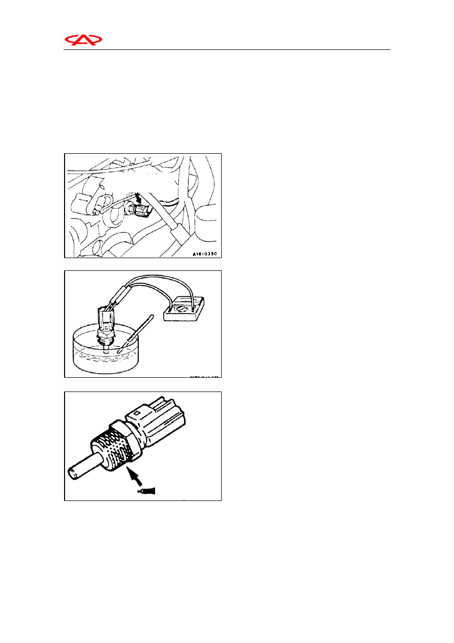
I. Engine coolant temperature 

sensor   


Construction feature--It is a thermal 

resistance installed in the outflow terminal of 

engine cooling system, which will test the water 

temperature and turn it to a signal. The signal is 

transmitted to ECU. The signal is input to 

calculate and correct the injection driving time. 


Check 


Caution: Not to touch the connector (resin part) 

with tools when disassembling and installation. 

(1) Disassemble the engine coolant temperature 

sensor. 


(2)Place the temperature sensor part of the coolant 

temperature sensor in hot water to check 

resistance. 

Standard value: 

  0℃,resistance is 2.1—2.7KΩ; 

20℃,resistance is 2.1—2.7KΩ; 

40℃,resistance is 0.9—1.3Ω; 

80℃,resistance is 0.26~0.36KΩ 


(3)If the resistance deviate off the standard value 

too much, the sensor should be replaced.     

(4)Coat sealant on the rippling part. 

Regulated sealant: 3M screw nut fastening 

NO.4171 or equivalent. 

(5) Installation coolant temperature sensor and 

tighten to the assigned torque. 

Fasten torque: 29N.m. 

Coolant Temperature
sensor  

Chery Automobile Maintenance Manual


23 


Error code NO.21engine coolant temperature 
sensor system 

Possible reasons 

Check area 


Ignition switch ON 


60 seconds after ignition switch turned to On position or after 

engine start   

Setup condition 


Sensor output voltage keeps above 4.6V for consecutive 4 

seconds (equals to engine water temperature below-45℃). 


Sensor output voltage keeps below 0.1V for consecutive 4 

seconds (equals to engine water temperature 145℃ or more) 

Check area 


Ignition switch ON 


Engine speed approx. above 50rpm 

Setup condition 


Sensor output voltage raises from below 1.6V (equals to 

engine water temperature above 40℃) to above 1.6V (equals to 
engine water temperature below 40℃) 


Then the sensor output voltage keeps at above 1.6V for 5 

minutes. 


Engine coolant temperature sensor error 


Connector of engine coolant temperature sensor contact 

defeat, wiring open loop or short wiring 


Engine ECU error 


Check engine coolant temperature sensor 

Abnormal

Repair 

Normal

Measure  connector  for  engine  coolant
temperature sensor  


Disassemble joint and check terminal

on the harness side 


Check voltage between 1#Terminal and

the ground (ignition switch ON) 

Normal:4.5~4.9V 
Conductivity  between  2#  terminal  and 
ground 
Normal: conductivity 

Normal 

Abnormal

Check D zone connector of harness ECU 
 

Normal

Check failure 

Abnormal

Check wiring between coolant temperature sensor and ECU。

Abnormal

Repair

Abnormal

Repair

Normal

Check  engine  coolant  temperature  sensor

harness joint 

Abnormal 

Repair 

Normal

Check failure 

Replace engine ECU 

Abnormal

Connector for 
coolant temperature sensor 

Chery Automobile Maintenance Manual


24 

T

II. 

T

Crank angle sensor 


Type—Hall type 

Crank angle sensor of B11 vehicle 

engine includes Hall flip-flop, permanent 

magnets, and shielding board, etc. A group of 

magnets are installed in the front of engine 

cylinder, one of which is embedded in the 

Hall flip-flop (electricity goes through current 

vertically as shown). Shielding board is 

installed in the front of crank and rotates with 

it, between the two magnets. On the flange, 

there are rectangular notches of same quantity 

as cylinders. The notches generates 

rectangular voltage wave by Hall flip-flop 

through flux and output to ECU through 

terminals and to control the working status 

(spray nozzle driving time, ignition time, idle 

airflow, connect and disconnect of EGR and 

vapour pollution and control system) of the 

executive devices by logic operation. 


1—ground(normal conductivity) 

2—connect to Pin D19 of ECU(IG: normal 

status  4.8—5.2V when switch on) 

3—connect to ignition switch (IG: normal 

status is battery voltage when switch on) 

D19---when motor on the voltage is 0.4—

4.0V;when idle the voltage is 1.5—2.5V. 


Crank angle sensor
connector 

2

Trigger signal

Hall 
flip-flop 

Shielding 
plate

Supply current I 

Permanent magnet


Chery Automobile Maintenance Manual


24 


Error code NO.22 crank angle sensor system   

Possible reasons 

Check area 


Rotate engine (tap engine) 

Setup condition 


Sensor output voltage has no variation for continuous 4 

seconds (no input of pulse signal) 


Crank angle sensor error   


Harness connector contact failure, sensor disconnect or 

short wiring 


Engine ECU failure 


Crank angle sensor connector 

3

Measure crank angle sensor connector 


Connect test wiring between joints:MB998478 


Voltage between Terminal 2# and ground(motor on)normal:0.4~

4.0V 


Voltage between Terminal 2# and ground(motor idle sped)normal:

1.5~2.5V 

Norma

l

Replace engine ECU 

Abnormal


Measure crank angle sensor connector 
   Disconnect joint and measure wiring side. 
1.voltage  between  terminal  3#  and  ground  (ignition
switch ON) 
normal:battery voltage 
2.voltage  between  terminal  2#  and  ground  (ignition
switch ON) 
normal:4.8~5.2V

Norma

Check sensor connector

Abnorm

al 

Repair 

Norm

al


Check failure 

Abnormal


Replace crank angle sensor 

1.Abnorm

al

Check harness between crank angle sensor and 

control relay. If necessary, repair it.

2. abnormal 

Check connector of harness 
in D zone

Abnormal 

Repair

Norm

al 

Check failure 

abnorma

l

Check wiring between crank 

angle sensor and engine ECU

Abnormal 

Repair

Norm

al


Replace engine ECU 

3.Abnorm

al

Check harness between crank angle sensor and

ground. If necessary, repair it.


Content   ..  73  74  75  76   ..