Chery B11. Manual - part 72


  Index      Chery     Chery B11 - service repair manual


Search            


Content   ..  70  71  72  73   ..


Chery B11. Manual - part 72


  Chery Automobile Maintenance Manual

11

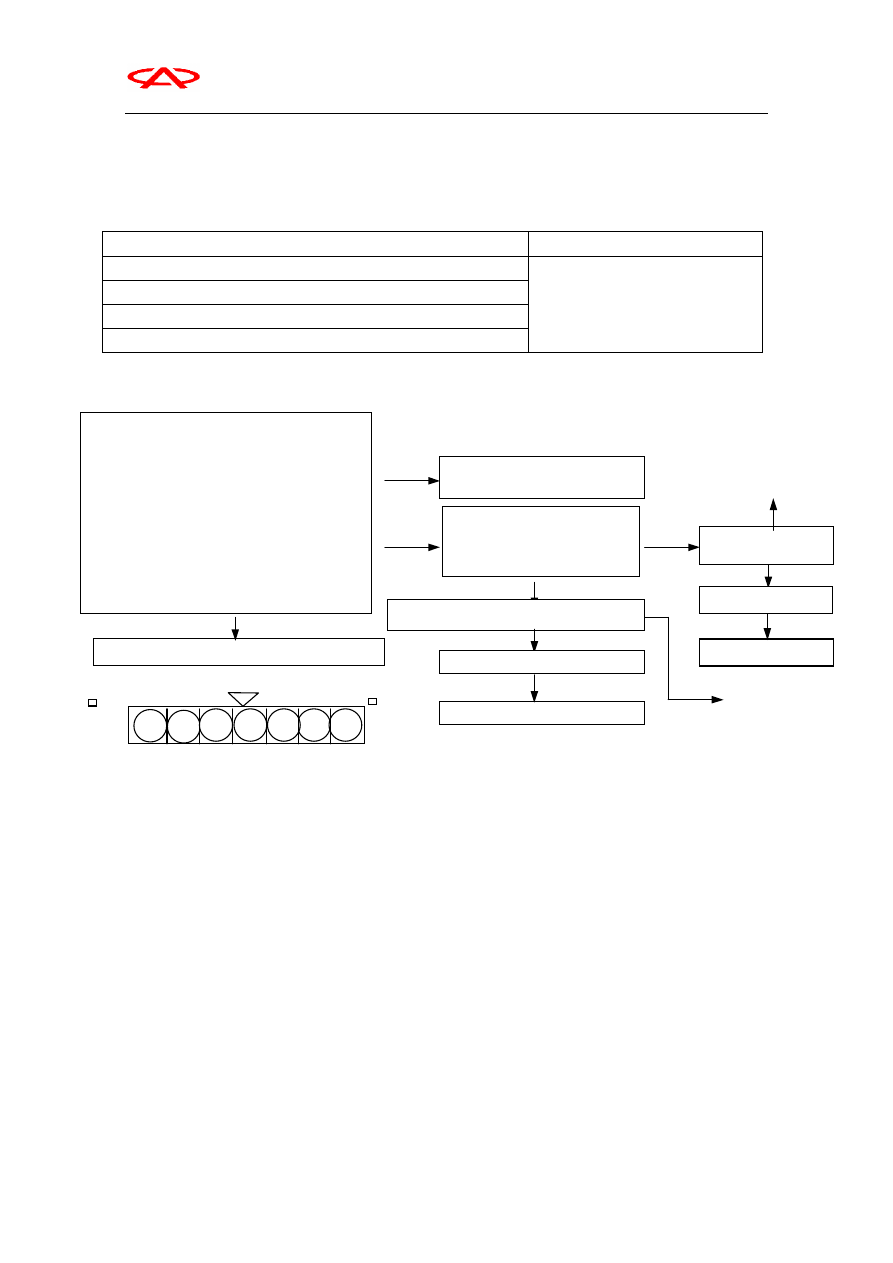
1.  Diagnostic Troubleshooting

Code 12             Airflow Sensor System

Possible Reasons

Check Area

A

Engine speed is above 500r/min.

Setup condition

B

Sensor output frequency last 4 seconds below 3Hz.

1

Airflow sensor failure

2

Connector contact defect of airflow

sensor, wiring open loop or short wiring

3

Engine-ECU failure

Measure airflow sensor

l

Connect test cable MB991709 between

airflow sensor and harness connector.

1.  The voltage between 3# terminal and

ground (at engine idle speed)

Normal voltage: 2.2-3.2V

2.

The voltage between 7# terminal and
ground (at engine idle speed)

Normal voltage: 0-1V(at engine idle speed)

6-9V(3000rpm)

Normal

Replace engine ECU

1.Abnormal Check the circuit of airflow

sensor

2.Abnormal

Check D zone terminal of engine ECU

l

Connect connector

l

Voltage between D20 terminal and

ground

l

Ignition switch: on (6-9V

normal)

Abnormal

Check airflow
sensor connector

Abnormal

Repair

Normal

Check D zone connector of engine ECU

Normal

Check failure

Abnormal

Replace engine ECU

Normal

Check failure

Abnormal

Replace airflow sensor

Abnormal

Repair

1

2

3

4

5

6

7

Airflow Sensor Connector

  Chery Automobile Maintenance Manual

12

II. Throttle Position Sensor

1.Type

Potentiometer

2.Structure Feature

Position sensor is combined with idle speed switch.

It includes resistance loop, conducting device

and mobile contact point. The mobile contact point is

linked to throttle axle and sliding on resistance loop,

which change resistance impedance to affect output

voltage. If ECU detects different throttle position, it

will calculate the drive time of fuel injection

according to the voltage signal.

D11--Sensor power supply (12V)

D14--Throttle position sensor

When ignition switch in ON, the voltage of idle

speed position is 0.3-1.0V and the voltage of wide

open throttle is 4.5-5.5V.

Check

Remove harness joint from TPS joint.

Measure the resistance value between 1# and 3#

terminal from TPS joint side.

Standard Value

3.5

6.5K

Measure the resistance value between 1# and 2#

terminal from TPS joint side.

Normal Status

Throttle open gradually from idle position until it is

wide open. The resistance value is proportionable to

the open angle of throttle, otherwise please replace

throttle position sensor.

Throttle Position Sensor

  Chery Automobile Maintenance Manual

13

Adjustment

1

Connect MUT-II to diagnostic troubleshooting

connector.

2 Insert intermission gauge into the place between

fixed SAS and throttle pole as follow (vehicle
without positioning control system) . The thickness
of intermission gauge is 0.45mm.

Vehicle with positioning control system

Insert a 1.4mm-thick intermission gauge into the
place between fixed SAS and throttle pole. The
insertion depth is 3mm.
Note: The insertion depth can’t be more than 3mm.
Otherwise the open angle of throttle pole will be
more than pre-defined angle, which will cause
incorrect adjustment.

3

Turn ignition switch to ON (don’t start on

engine)

4

Loosen installation bolt of throttle position

sensor and then turn around throttle position sensor
counter-clockwise to its limitation position.

5

Under the status, check if idle speed position

switch is ON with MUT

II “DATA LIST” or

ohmmeter.

6

Turn around slowly throttle position sensor

clockwise until idle speed position signal is turned
from ON to OFF. And then fasten the fasten bolt of
throttle position sensor.

7

Check the output voltage of throttle position

sensor.
Standard Value

400

1000mV

8

If different from standard value, please check

throttle position sensor and related harness.

9

Remove thickness gauge.

10

Turn ignition switch to OFF and remove

MUT-II.

  Chery Automobile Maintenance Manual

14

Idle Speed Position Switch Check

(1) Remove harness joint from TPS joint.

(2) Check the conductivity between 1# and 2#

terminal on throttle position sensor joint.

Normal Status

3

  If it disobey specification requirement, please

replace throttle position sensor.

Note: After replacement please adjust idle speed

position switch and throttle position sensor.

Accelerator 

Pedal 

Conductivity

Step on

Non-conductible

Loosen

conductible

0


Content   ..  70  71  72  73   ..