Chery A15. Manual - part 55


  Index      Chery     Chery A15 - service repair manual


Search            


Content   ..  53  54  55  56   ..


Chery A15. Manual - part 55


SHIFT ADJUSTMENT 

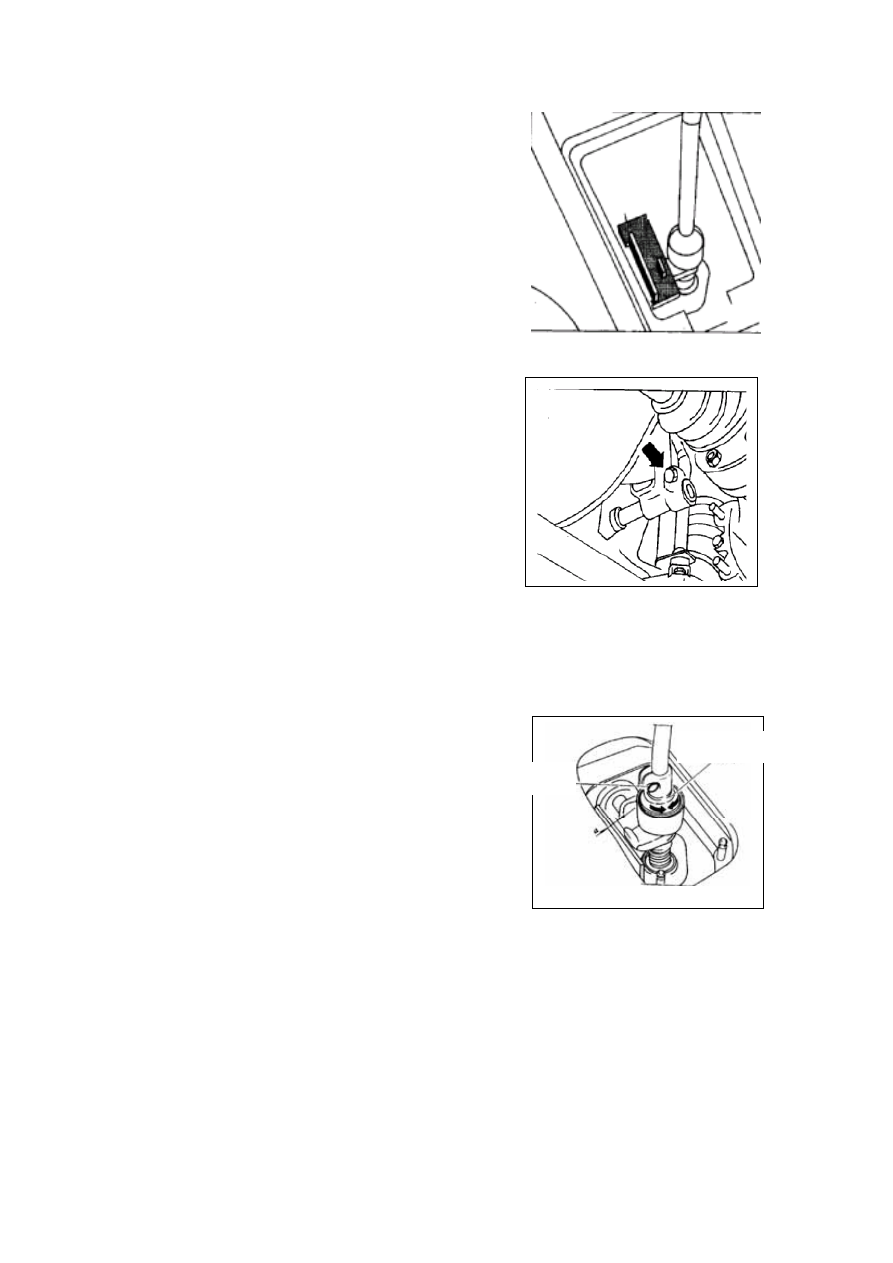
Neutral positioning: 

——Disassemble gearshift knob and protective 

cover and fix the gearshift knob according to 
the positioning requirement, see the chart (the 
black one is positioning assist)   


——Leave the pipe clamp at its natural position. 

——Clamp nut, fasten by 25Nm. 

——Try all the shifts, gear shifting should be 

smooth and without stop, secure the validity of 
the reverse gear lockup.


  Fine adjustment: 

——After a long time using of the vehicle, there will 

be wear and tear between gearshift mechanism 
parts which makes the space between shifts 
too much bigger and difficult for gear shifting 
then you need fine adjustment. 

——Check the 1

st

 shift position, loosen nut B, do as 

the chart show: Put transmission on 1

st

 shift 

position, fasten bolt B by adjusting the 
eccentric ring position to a=1.5mm. 

— — Fasten clamp bolt (the transmission on the 

neutral position), try all the shifts, which should 
be smooth and easy. 

——Try all the shifts gear shifting should be smooth 

and without stop, secure the validity of the 
reverse gear lockup. 


Bolt

Eccentric Ring 


J-11


TRANSMISSION RESOLUTION 


1. Fastening Screw (4 Pieces, Fasten Moment Is25n.M)    2. Fixing Screw (2 Pieces, Fasten

Moment Is 25N.M)     3. Bleed Bolt    4. Transmission Rear Housing   5. 5

th

 Synchronizer

Assembly   6. 5

th

 Driven Gear Snap Ring   7. 5

th

 Driven Gear   8. 5

th

 Fork Pad

9. 5

th

 Fork Assembly        10.    5

th

 Gear Holder Fixing Turnbuckle    11. Dish Washer   12. Shim


J-12


1. Input Shaft Rear Bearing Plate Screw (4 Pieces, Fasten Moment Is 15N.M) 2.  Transmission

Housing Assembly 3. Fixing Screw (12 Pieces, Fasten Moment Is 25N.M)    4. O-Ring    5. Gearshift

Shaft Plug Cover 6. Gearshift Shaft Pressing Spring 7. Gearshift Assembly 8. Gearshift Positioning

Holder Assembly 9. Pressing Spring-Damper Ring 10. Output Flange 11. Output Flange Dish Washer

12. Output Flange Snap Ring    13. Flange Cover    14. Idler Shaft Fixing Screw    15. Fixing Bolt (2

Pieces, Fasten Moment Is 25N.M) 


J-13


1. 4

th

 Driven Gear Snap Ring    2. 4

th

 Driven Gear    3. 3

rd

 Driven Snap Ring    4. 3

rd

 Driven Gear    5.

2

nd

 Driven Gear    6. 2

nd

 Synchronizer Ring    7. 2

nd

 Roller Bearing    8. 2

nd

 Roller Bearing Lining    9.

1

st

 -2

nd

 Synchronizer Assembly  10. 1

st

 Synchronizer Ring  11. 1

st

 Driven Gear  12. 1

st

 Roller

Bearing  13. Bearing Holder Fixing Bolt 14. 1

st

 Roller Bearing Snap Ring  15. Output Shaft

Intermediate Bearing Holder 16.  Differential Assembly  17. Damper Ring  18. Pressing

Spring-Damper Ring    19. Output Flange 20. Output Flange Dish Washer    21. Output Flange Snap

Ring    22. Output Flange Cover    23. Fork    24. 5

th

 Fork Sleeve    25. 3

rd

-4

th

 Fork    26. 5

th

 Fork Guide

Plate   27. Reverse Fork Guide Plate   28. 1

st

-2

nd

 Fork  29. Input Shaft Assembly  30. Idler Shaft

31. Idler Assembly    32. Clutch Housing assembly 

J-14


Content   ..  53  54  55  56   ..