Chery A series. Manual - part 112
 

  Index      Chery     Chery A series - service repair manual


Search            copyright infringement  


Content   ..  110  111  112  113   ..


Chery A series. Manual - part 112


part of the battery away from water. 

Connect the battery to the charger, and adjust 
the charging current accordingly. 


As heat discharged by the exhaust manifold could damage the generator, you must 
ensure that the heat discharging guard and insulation device are firmly installed on the 
generator. 
 
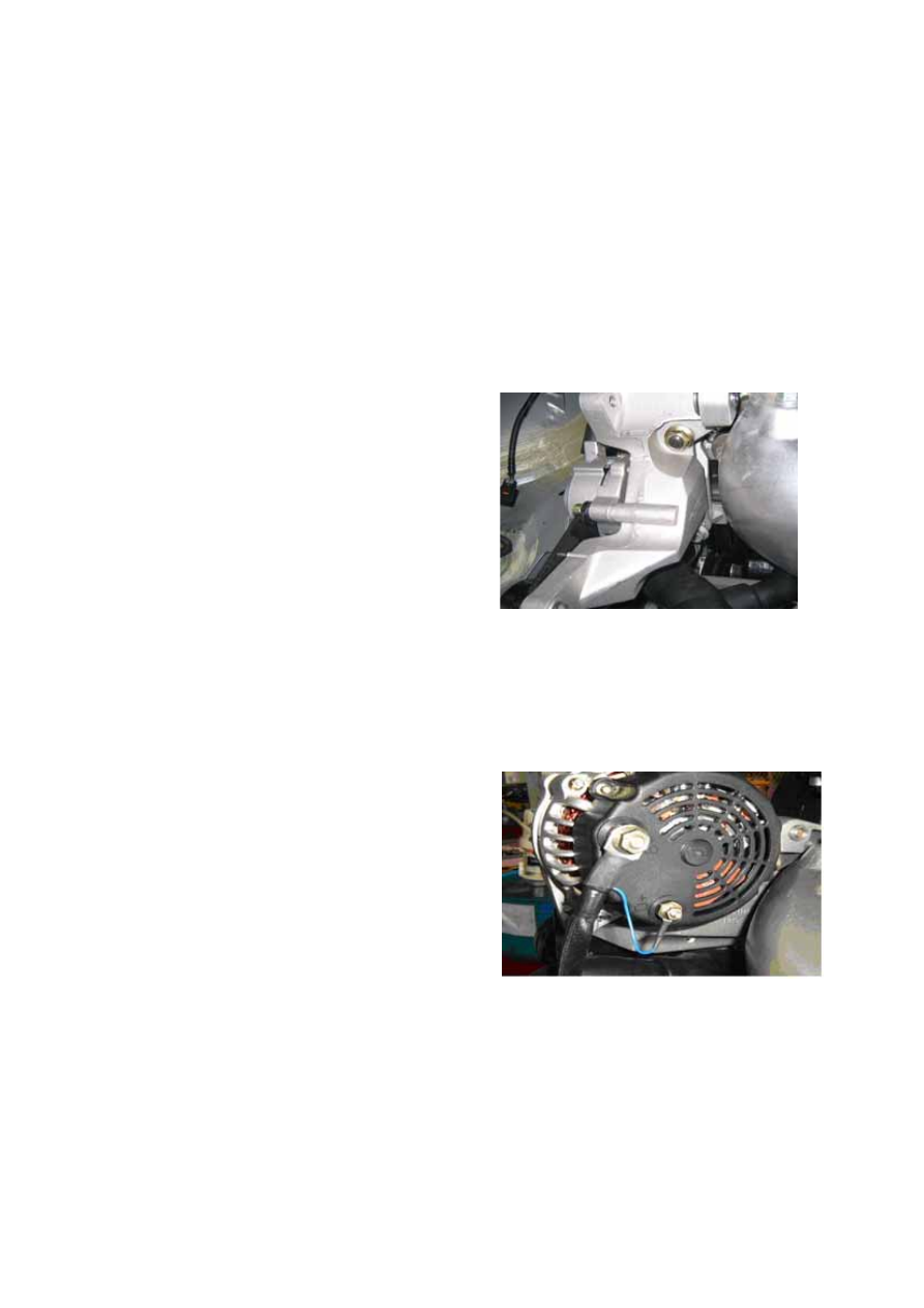
Installation of generator bracket: 

Disconnect the negative grid of the battery. 

Mount the double-ended stud on top of 

cylinder cover. 

Install the bracket of generator. 

Tighten flange nut of the double-ended stud 
and bolt on the cylinder body, the tightening 
torque should be 40±4Nm. 

The installing steps are reverse to those for 
removal. 


Installation of generator: 

Disconnect the negative grid of the battery. 

Align one end of the generator with the 

installation hole of bracket, and push it in by 
force until the installation hole and the shaft 
hole of the generator are aligned. 

Use a long bolt and an Allen screw 

respectively to install the generator on its 
bracket, with a tightening torque of 
25±2N.m. 

Connect the positive power source wire with 
the generator and the cable lug of the battery 
warning lamp to the wiring terminal. 

Note: The wiring harness must not be 

grounding so as to avoid from 
catching fire. 

The installing steps are reverse to those for 
removal.


T-6


Installation of driving belt and tensioner 
assembly: 

Disconnect the negative grid of the battery. 

Use 3 M8 Allen screws to install the 

tensioner assembly on the bracket of the 
generator, with a tightening torque of 
25±2N.m. 

Install the multi-wedged belting; Pull out the 
pin on the tensioner assembly so as to 
tension the driving belts in the tensioner 
pulley. Inspect the driving belts to see 
whether they are all inserted properly in the 
driving wedge of the pulley wheel. 

The installing steps are reverse to those for 
removal.


Adjusting method of multi-wedge belting 
and tensioner assembly alignment: 

—Disconnect the negative grid of the battery. 

—Use spanner to rotate the engine crankshaft 

belt pulley to drive the multi-wedged belting 
for at least one revolution. 

—Observe the alignment status of the multi 

-wedge belting and tensioner assembly, if 
the multi-wedge belting center exceeds the 
tensioner assembly center, then remove the 
tensioner assembly and add spacers to adjust 
the centering. 

The installing steps are reverse to those for 

removal.


Overhaul of generator: 

—Inspect the accuracy of deflexion and 

tension value of the driving belt, if it does 
not comply with the requirement, then the 
driving belts should be replaced. 

—Shut down all the electro-devices, turn the 

ignition switch to start the engine, inspect 
the rotation process of the engine to see 
whether the rotation of generator is smooth 
without any noise. 


T-7


—Use voltmeter to measure the voltage value 

of the generator output terminal. 

Standard value: Engine idling; Temperature: 20

, Output voltage: 13-15V. 

—Switch on the following devices and observe 

the increase of readings of the voltmeter: 

• Headlamp 

• Air conditioning 

• Back window defroster 


INSPECTION OF GENERATOR 

Warning lamp of generator 

1. Confirm that the battery has been fully charged; 

● If it necessary, the battery should be charged. 

2. Confirm the accuracy of deflexion and tension values of the wedge type belts. 

● If it does not comply with the requirement, then replace it with a new type of wedge type 

belt. 

3. Turn on the ignition switch, and inspect the generator warning lamp to see whether it is 

indicating. 

● If it does not comply with the specified requirement, then inspect the generator warning 

lamp, or check whether the generator connectors are connected firmly. 

4. Confirm whether the generator warning lamp is off after the engine is turned off. 

● If it does not comply with the requirement, then inspect the instrument connector to see 

whether they are connected properly; if the instrument is malfunction free, then you need 
to further inspect the generator itself to see whether there is any short circuit. 


T-8


REMOVAL/INSTALLATION OF STARTER 

Warning: 

When connecting wires of the battery are in on-state, and at this time if you contact the 
generator terminal to the car body, sparks will happen. This may cause body injury, fire 
and the sparks may damage the electrical components. Therefore before carrying the 
following operation, you must disconnect the negative grid of the battery first. 

Disconnect the negative grid of the 

battery. 

Apply lubricating grease of about 5 

grams evenly on the inserting shaft of the 
starter. 

Insert the starter into housing of the 

clutch. 

Screw three bolts and tighten them,(one 
of the bolts is M10×1×35), with the 
tightening torque of 40±4Nm. 

Connect the wiring harness to the 

positive grid of the starter, and the starter 
wiring harness connector. Pay attention 
not to ground the wiring harness so as to 
prevent short circuit and catching fire. 

The installing steps are reverse to those 
for removal.


OVERHAUL OF STARTER


No load test: 

Verify that the battery is fully charged. 

Close the circuit of the starter, battery, voltmeter and ammeter according to the following 
diagram. 

Initiate the starter and check whether it operates smoothly. 

When the starter is rotating, measure its voltage and current values. If these values do not 
meet the requirements, then replace the starter. 


T-9


Content   ..  110  111  112  113   ..