Chery A series. Manual - part 73
 

  Index      Chery     Chery A series - service repair manual


Search            copyright infringement  


Content   ..  71  72  73  74   ..


Chery A series. Manual - part 73


Illustration 16

Check the oil seal of the stop collar assy.
Refer to Illustration 16 

Check (3): Inspect if there is flake or indention 
on the working surface of the oil seal 30 of the 
stop collar assy and damage on the lip. Examine 
if there is scratch on the inner surface of the 
housing 34 and damage on the O rubber ring 28. 
Replace the oil seal, housing or O rubber ring, if 
necessary. Apply the white special grease on the 
inner and outer surface when install a new one. 


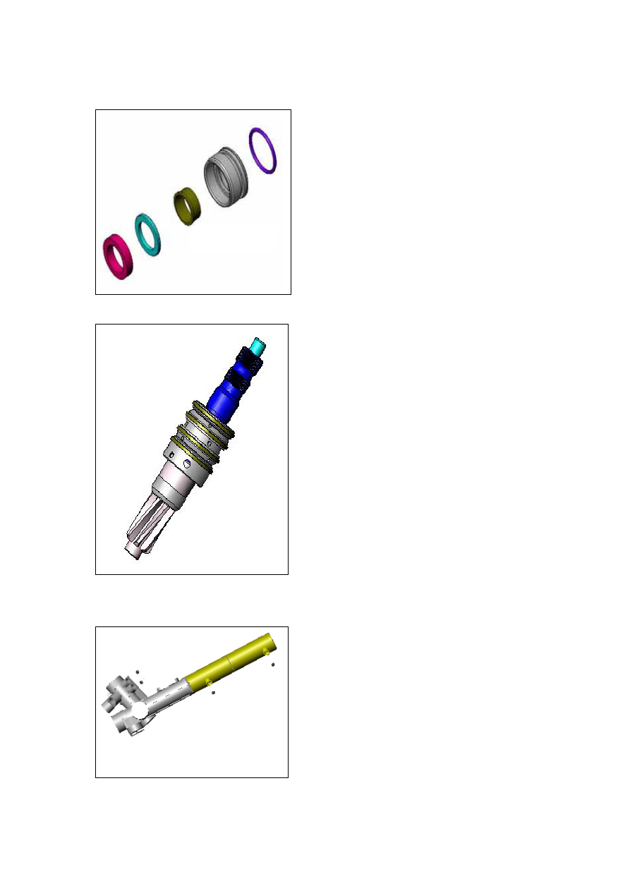
Illustration 18

Illustration 17


Valve core assy


Check (4): Inspect if there is crack, damage, 
flake or deformation on the rack surface of the 
pinion shaft of the valve core assy 13. Replace 
the valve core, if necessary. Examine if there is 
damage on the seal ring 8 of the valve core assy. 
Replace with a new one, if necessary. Remove the 
seal ring with a screwdriver when replace.   

Precaution: Do not damage the valve bush. 
Enlarge the new seal ring with a special 
purpose tool and install the enlarged one on 
the valve bush of the valve core assy and then 
shape it with a set sleeve. 


Check the conical connectors which are 
connected with the hull assy (Refer to 
Illustration 18) 

Check (5): Inspect if there is scratch or damage 
on the surface of the conical connectors 16 and 18 
which are connected with the hull and the oil 
reservoir connectors. Replace with a new one, if 
necessary. When replace, remove the conical 
connector with a special purpose tool and beat 
lightly a new one with a plastic hammer. 


N-13

Assemblage of the Steering Mechanism 

Preparation: 

 Clean all components in clean organic solvents before assemblage, then dry them with a 

blower 

Precaution: Be careful during operation. The organic solvent is flammable and 

explosive, keep it away from any tiny sparks. Otherwise, it may lead hurt 
or even death. 

Precaution:    Make sure to wear the goggles while using the compressed air. 

 Lay the clean components separately and avoid the collision or scratch. 

Replace all the oil seal, seal loop and seal ring. Apply the white special grease on the 
O-ring and oil seal of the seal sections. 

 Get the replacing components ready every component must be qualified before 

assemblage. 

Precaution: When replace, all the set bolt, adjusting screw, seal component, lock nut 

and the other components must be conformed to the technical specification 
of Chery and can not be substituted arbitrarily. 

 Get the clean MoS

2

Lithium lubricating grease or the same performance grease ready 

during assembling. 

Precaution: If the unclean grease is used, the seal components would be damaged or 

scratched, which will impact the steering power and result in accidents. 

Assemblage 

Precaution: Do not twist any seal components during assembling. 


Illustration 19

Install the rackRefer to Illustration 19 
·Apply MoS

2

Lithium lubricating grease on the 

rack of the rack assy 31   
·Protect the rack with the vinyl tape. Fix the 
rack piston assy in the oil cylinder hull, then pull 
out the vinyl tape and check if it is complete.                


N-14

 
Install the valve core assyRefer to 
Illustration 20
 

·Install the valve core assy 31 as the direction 
of the skew gear tooth into the hull oil reservoir 


Install the stop collar assyRefer to 
Illustration 21
 

·Coat the cylinder side rack 31 with vinyl tape. 

·Apply the white special grease on the inner 
surface of the oil seal 30 

·Press the stop collar assy into the oil reservoir 
body 17            

·Install the wire stopper 36 with a wire caliper 
and position the stop collar assy. 

·Install the bearing 12, the upper oil seal 11 and the snap ring for hole 10. 


Illustration 22

Illustration 21

Illustration 20


Install the support device of the rack  Refer 
to Illustration 22
   

·Apply the MoS

2

Lithium lubricating grease on 

the slot area of the rack holder 23 

·Install the rack holder 23 into the hull oil 
reservoir assy 17. 

·Install the spring 22. 

·Screw the adjusting plug 21 into the hull oil 
cylinder assy with a special purpose tool and 
screw back 30º-40 º. 

·Screw the lock nut 20 on the adjusting plug. 

·Install the limiting plug of the rack end. 

·Apply the 5242 sealant on 1/4 circle thread of the hexagon flange bolt 24 and screw it to the 
specified position of the pinion shaft. The tightening torque is 20~30N.m 

·Screw the plug cap 26 1-2 threads, then apply proper quantities 5242 sealant onto the thread 
of the plug cap and fix it into the hull. The torque is 35~45N.m. 

N-15

Install the left and right oil tube assyRefer 
to Illustration 23


Illustration 24

Illustration 23


·  Install the new conical connectors 18 and 16 
on the ends of      the left oil tube assy 19 and 
right oil tube assy 27. 

·Tighten the left and right oil tube assy with the 
tightening torque of 15~25N.m 


Assembling and adjustmentRefer to 
Illustration 24
 

·Adjust the adjusting plug 21 with a special 
purpose tool. 

· Cover the input shaft with the crank handle 
and rotate it to feel if it turns smoothly. 

·Apply the 5242 sealant on the 1/4 circle thread 
of the adjusting plug 21 which is close to the 
hull, fix the adjusting plug and screw the lock 
nut 20 with the tightening torque of 40~50N.m 


If it is easy to adjust the lock nut of the rack holder, it is not required to remove the 

steering gear from the vehicle. Therefore the adjustment can be completed on vehicle. 

 
a)Check the clearance 

Pull the steering tie rod to make it swing back and forth by hand to ensure that there is no 
clearance between the rack and the pinion shaft.   

Hint: It is not needed to adjust it if it is normal during the check. 

b) Adjust the lock nut of the rack holder to eliminate the clearance


If there is the clearance, loosen the lock nut 18 and screw the adjusting plug 19 clockwise 
until the clearance can not be felt between the rack 29 and the pinion shaft. Screw the 
adjusting plug 19 back about 30º~40 º, and then apply the 5242 sealant on the lock nut 18 and 
screw it with the tightening torque of 40~50N .m. 

N-16


Content   ..  71  72  73  74   ..