Chery A series. Manual - part 72
 

  Index      Chery     Chery A series - service repair manual


Search            copyright infringement  


Content   ..  70  71  72  73   ..


Chery A series. Manual - part 72


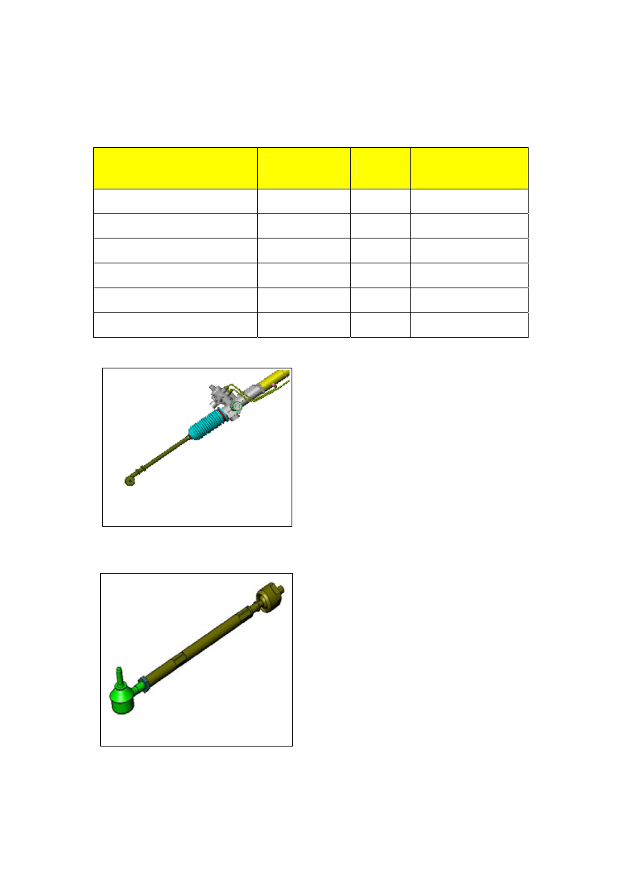
Removal and Dismantling of Steering Gear 

Repair and adjust after the removal of the steering gear   

Tightening Torque for the Fastener Set Components  (Shown as the table below) 

Description 

Specification 

Quantity

Tightening Torque

N.m) 

Hexagon flange bolt 

Q1840812 

20~30 

Plug cap 

M30X1.5 

35~45 

Lock nut 

M32X1.5 

40~50 

Oil tube connector bolt 

M12X1 

15~25 

Inner ball joint-rack 

M12X1 

70~90 

Hexagon nut - outboard joint 

M14X1.5 

4.9~9.8 


Fix the steering Gear

Refer to Illustration 5 


Illustration 6


Illustration 5

·Fix the steering gear on the vises and keep the         
input shaft flatly. Take off plug cap of the oil 
inlet and the outlet to discharge the oil. Rotate 
the input shaft for several times to discharge the 
oil from the steering gear. 


Remove the left and right steering link assy 
(Refer to Illustration 6) 

·Loosen the lock nut 3 of the left and right    
steering link assy, and then remove the     
outboard joint assy 1 and 2 


N-9


Illustration 7

Remove the left and right protector (Refer to 
Illustration 7) 

·Remove the single ear no-level clip 6, then  
the clamp 4 and take off the protector 5. 


Remove the left and right oil tube assyRefer 
to Illustration 8
 

·Loosen the joint nuts of the left oil tube assy   
19 and right oil tube assy 27, and then remove 
the left and the right oil tube assy. 


Illustration 9

Illustration 8

 
Remove the inner ball joint ( Refer to 
Illustration 9
 

·Lock the rack with an open-end assistant, and 
screw up the inner ball joint assy 7 with another 
assistant. 


N-10


Illustration 10


Remove the support device of the rack 
Refer to Illustration 10 

·Screw down the lock nut 20 with an special 
purpose spanner first, then the adjusting plug 21, 
and remove the spring 22 and the rack holder 23 
in sequence.. 


Remove the valve core assy ( Refer to 
Illustration 11
) 


Illustration 11

·Clamp the hull oil cylinder assy 17 which is 
used to fix the valve core assy on the bench 
vises and the upper limiting plug of the rack 
end. Remove the hexagon flange bolt 23 and 
the plug cap 26 of the valve core tail with a 
special purpose tool. Then remove the valve 
core assy 13. Cover the protector on the pinion 
shaft spline, and take off the oil seal 11 and the 
bearing 12(Do not damage the lip of the oil 
seal) 


Remove the stop collar assy ( Refer to 
Illustration 12


Illustration 12

·Remove the round wire snap ring 36 with a  
wire caliper, then the stop collar 35 and the O 
rubber ring 28 


N-11


Remove the rack assy  Refer to Illustration 
13
 

· Press the rack assy 31out with a special 
purpose tool. 


Check and Replacement of the Components of the Steering Mechanism 

Check the steering rack piston assyRefer to 
Illustration 14
 

Check(1):Inspect the stagger of the rack 31 of 
the rack piston assy, which the maximum value 
is 0.15mm. Examine if there is flake or 
indention on the rack surface and crack or 
damage on the working surface. Check if there 
is wear or damage on the back surface. Replace 
the rack piston assy, if necessary. Check the 
damage of the piston ring 32 and the O rubber 
ring 33 of the piston. Replace both, if necessary. 
Remove the piston ring 32 and O rubber ring 33 
with a screwdriver. 

PrecautionDo not damage the rack 31. Apply the power steering oil on the new O 
rubber ring 33, and then install it. Enlarge the piston 30 with finger. 

PrecautionDo not enlarge the piston ring excessively. Install the new piston ring 32 on 
the piston of the rack piston, apply power steering oil on it, press it tightly with finger. 


Illustration 15

Illustration 14

Illustration 13


Check the bearing of the rack hull assy 
Refer to Illustration 15 

Check (2) 

Examine if there is indention or 

damage on the lower bearing 25 of the hull oil 
reservoir assy 17 and if it can rotate freely. 
Replace it, if necessary. Apply the white special 
grease on the installation position of the bearing 
when install a new one.


N-12


Content   ..  70  71  72  73   ..