Chery A series. Manual - part 71
 

  Index      Chery     Chery A series - service repair manual


Search            copyright infringement  


Content   ..  69  70  71  72   ..


Chery A series. Manual - part 71


REMOVAL/INSTALLATION OF STEERING COLUMN 


Removal and Installation of the Steering 
Column


·Remove the nuts on the steering wheel 

·Remove the upper and lower protector of the 

instrument cluster and the switch 

·Remove the instrument panel assy. (Please refer 

to the removal of the instrument panel) 

·Remove the joint bolt of the upper steering 

column bracket and the car body upper bracket.

·Grind away the safety screw and replace with a 

new one when installing. 

·Remove the joint bolt between the steering gear 

and the steering column (tightening torque: 
30N·m) 

·Install the steering column inversely according 

to the removal steps.


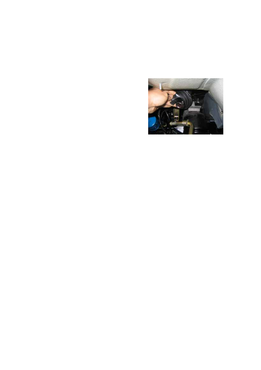
The inner spline of the steering gear is 

shown as the picture below: 


Removal and Installation of Steering Shaft and Steering Tube 

·Remove the clip. 

·Take off the serrated set bush and the steering gear lock housing from the steering column

·Draw out the steering shaft and press the lower bearing of the steering column out with a 

presser. 

·Disassemble the lock housing spring of the bracket ring steering shaft with a presser. 

·Assemble the steering column inversely according to the removal steps. 

Precaution 

·Apply a little grease around the lower bearing and the inner wall of the steering hose 

column lower end, press the lower bearing into the steering hose column using a 
presser.(Do not move the upper and lower universal joint of the guard column) 

·Adjust the relative height of the lock housing and the hose column according to the height 

of the pre-installed ignition lock cylinder and the combined switch cover.   

·Apply lithium base grease evenly around the contact ring. 


N-5

Disassembling Illustration of the Steering Column 


20 

1- Horn Button Cap;      2-Nut(40N·m)

;    3- Spring Washer;      4-Steering Wheel; 

5- Serrated Set Bush;    6-Spring;                      7-Lower Trim Cover        8- Upper Trim Cover

9- Steering Gear Lock Housing and Steering Column Switch;           10- Support ring;     

11-Steering Shaft;          12-Nut(30N·m)

;   13- Steering Universal Joint  

14- Hex Bolt                      15-Spring;                    16- Steering Column Lower Bearing   

17-Safty Screw;              18-Washer;                  19-Steering Tube;          20- Clip


REMOVAL/INSTALLATION AND CHECK OF STEERING GEAR 

Lift the whole vehicle at a designated safe 
place with a lifter 

·Remove the high and low pressure oil tube 
of the steering gear with torques of 45±3N·m 
and 30±3N·m respectively.     

·Remove the joint piece of the steering link 

·Remove the shift shaft bracket 

·Remove the front tube and the three way 
catalytic converter with torques of 60±3N·m 

Two bolts on one side of the steering gear are 
shown as the picture below. Tightening 
torque: 30±3N·m. 

N-6

and 25±3N·m respectively. 

·Remove the four bolts of the steering gear. 

·Remove the fixing bracket of the steering 

gear and the rubber hose. 

·Install the steering column in the reverse 

order of the removal.   

Note: 

The right picture shows the status of 

the power steering oil tube of the steering 

gear removed. 

The tightening torque for the hollow bolt 

which connects the high pressure oil tube 

and the power steering pump is 45±3Nm. 


REMOVAL/INSTALLATION AND REPAIR OF MAIN BODY OF 

STEERING GEAR 

Exploded view of the rack & pinion power steering gear 

Code                   Description                      Quantity 

1.                      Left pull rod outboard joint assy                                  1 
2.                      Right pull rod outboard joint assy                                1 
3.           Hexagon nut                                 2 
4.                      Clamp                                                                            2 
5.                      Rack shield                                                                    2 
6.                      Single ear no-level clamp                                              2 
7.                      Inner ball joint                                                                2 
8.                      Seal ring                                                                        4 
9.                      Dust cover                                                                      1 
10.          Snap ring for hole                             1 
11.                    Oil seal                                                                          1 
12.          Bearing                                     1 
13.          Valve core assy                               1 
14.          Bearing                                     1 
15.          Oil seal                                     1 
16.          Conical connector                             2 
17.          Hull oil cylinder assy                          1 

N-7

18.          Conical connector                             2 
19.          Left oil tube assy                              1 
20.          Lock nut                                     1 
21.          Adjusting plug                                1 
22.          Spring                                       1 
23.          Rack holder                                  1 
24.          Hexagon flange bolt                            1 
25.          Bearing                                      1 
26.


Plug cap                                                                          1 

27.          Right oil tube assy                             1 
28.          O rubber ring                                 2 
29.          Washer                                      2 
30.          Oil seal                                      2 
31.          Steering rack piston assy                        1 
32.          Piston ring                                   1 
33.          O rubber ring                                 1 
34.          Housing                                     1 
35.          Stop collar                                   1 

36.          Wire stopper                                 1 


N-8


Content   ..  69  70  71  72   ..