Chery A series. Manual - part 23
 

  Index      Chery     Chery A series - service repair manual


Search            copyright infringement  


Content   ..  21  22  23  24   ..


Chery A series. Manual - part 23


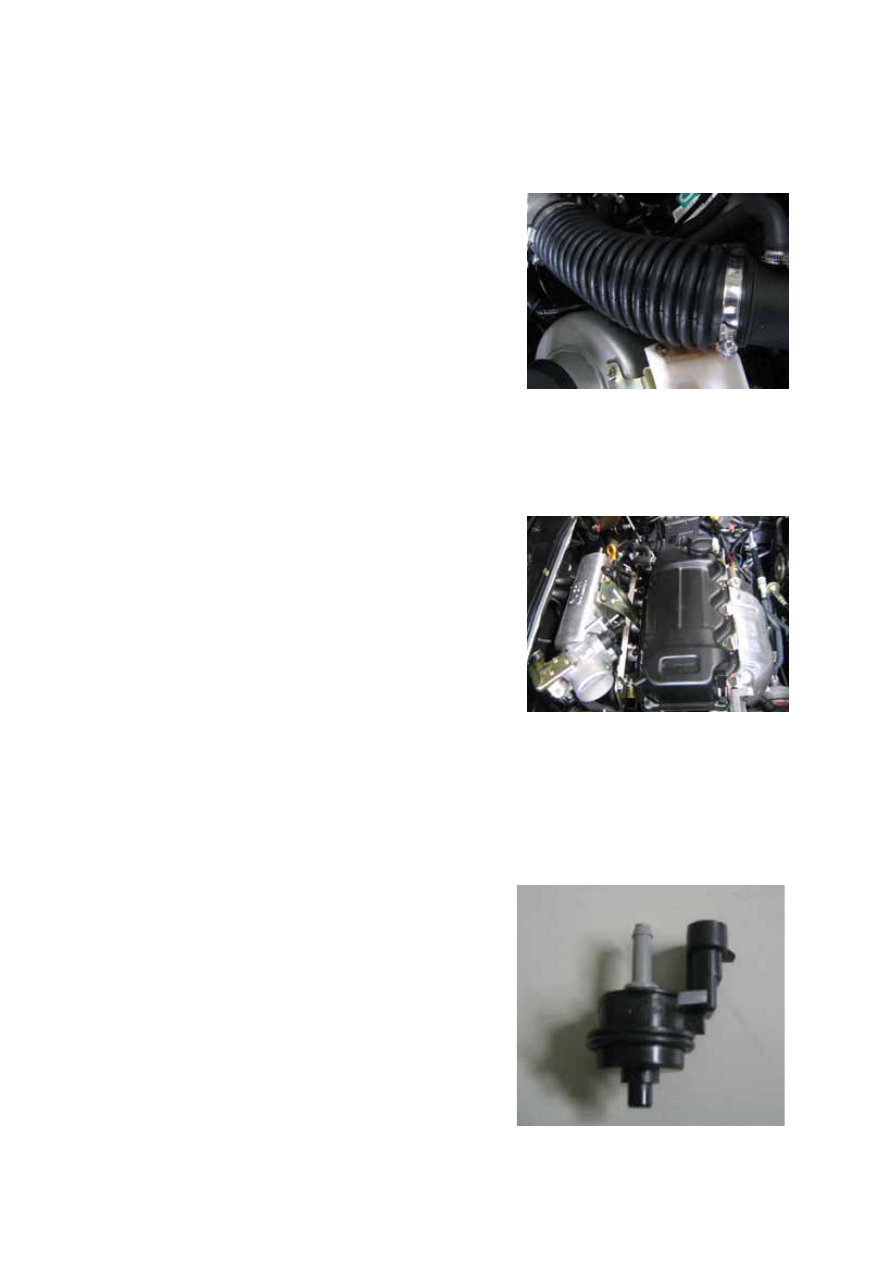
ASEEMBLY AND DISASSEMBLY OF INTAKE SYSTEM   

Remove accessories around the engine: 

1.Loosen fastening clamp, demount air 

cleaner and air intake hose.     


2.Remove throttle cable and clutch cable. 

3.Remove all intake pipes and vacuum 

hoses around engine. 

4.Put down water hose to discharge 

anti-freeze liquid. 

5.Disassemble the throttle position sensor/

canister solenoid/crankshaft position 

sensor/Injection nozzle / knock sensor 

and wire plugs on electric components 

like fuel pressure switch.


CANISTER SOLENOID AND INTAKE/EXHAUST PIPE 

Assembly: 

——Fix the solenoid on the intake manifolds 

with a semicircular clamp and tighten 
two inner bolts. 

——Install the solenoid intake pipe between 

the activated canister and the solenoid, 
then tighten the clamp around the intake 
pipe with special tool. 

——Install solenoid exhaust pipe between the 

throttle body and the solenoid. then 
tighten the clamp around the exhaust 
pipe with special tool.


F-7

OIL-VAPOR SEPARATOR


1.Oil-vapor separator      2. Air cleaner     3.Others---ventilating pipe in crankcase 


Working principle: 

Main function of the oil-vapor separator is leading gas in crankcase to intake manifolds 
through oil-vapor separator, which keeps pressure in crankcase within a certain range and 
prevent gas in crankcase from mixing and flowing out. Oil-vapor separator shall separate the 
oil vapor mixture passed the crankcase to avoid the oil entering into engine where it will 
generate carbon grains that causes engine wear. 

Oil-vapor separator assembly, air cleaner and ventilating pipe assembly is showed in fig. A 
connect to one interface on the engine valve cover; B connect to another interface on the 
engine valve cover; C connect to the crankcase interface; D connect to the intake manifold 
interface. Connect the ventilating pipe to the interfaces of oil-vapor separator, air cleaner 
by-pass hose and engine valve with spring clamp. 

Assembly and disassembly: 

Fix three iron-ventilating pipes to the bolts in engine intake manifolds using 4 M8 nuts 

with a tightening torque of 10±1Nm. 

Maintenance of fuel-vapor separator: 

Disassemble it per 5000km and wash it with lead-free gasoline, then blow it to dry.


E

F-8

EXHAUST SYSTEM 

OUTLINE  

Exhaust system inspection   

·Start the engine and inspect each exhaust system component for exhaust gas leakage. 

·If leakage is found, repair or replace as necessary.   

Exhaust system removal/installation   

Warning 

·When the engine and exhaust system are hot, they can badly burn. Turn off the engine 

and wait until they are cool before removing the exhaust system. 

Exhaust assembly and oxygen sensor position 


1. Oxygen Sensor        2. Catalytic Converter        3. Silencer 


OXYGEN SENSOR   

To gain max. conversion efficiency from catalytic converter, the engine oxygen sensor always 
keeps the concentration of fuel-gas mixture as chemical reaction equivalence ratio. 

The sensor shall realize closed loop controlling to the mixture concentration through 
measuring the proportion of oxygen in exhaust. 

Oxygen sensor is installed in the first section of exhaust pipe near manifolds. 

Oxygen sensor is a ZrO

2

 porcelain (1) with a thin platinum layer on its surface and one end is 

sealed with a protection pipe inserted in. (2), the outside bushed with a metal housing (3) to 
protect the sensor and to enable it to install on the exhaust manifolds. The outside of porcelain 
(b) is exposed in exhaust gas, the inside (a) communicate with outer surroundings. Working 
principle: voltages generated by electrode will change with the variation of oxygen 
concentration; oxygen sensor measure the components of the exhaust, thus ECU will obtain 

F-9

F-9

the mixture concentration value in time and change mixture thicker or thinner to make it 
always be close to chemical reaction equivalence ratio. The voltage range of which is 
0.980~1.020V. 

To reach working temperature rapidly (~300°C), a resistor (4) installed in the sensor can 
shorten the starting electric time of the porcelain. It means sensor can be installed in cold area 
of exhaust hose. If mixed gas concentration is thinner than chemical reaction equivalence ratio 
when working in full speed, ECU will give signal to the oxygen sensor to add mixture thicker 
(half-closed loop). 

Oxygen sensor doesn’t work under cut-off and full load condition, which is called open loop.


Recovery: 

If fault occurs in sensor or resistor, all information will be ignored and the whole system will 
work as an opened loop system.


Oxygen sensor test procedure: 

If diagnosis tester displays signal as “lambda sensor error “, please check: 

——

If there is air leakage in every manifold, pipes, brake booster, exhaust gas and fuel-vapor

re-cycle system. 

——

Spark wear and efficiency of high voltage wire insulator. 

——

If timing and positioning of TDC (top dead center)/rotate speed sensor is right or not. 

——

Tappet clearance and engine compression ratio. 

——

If supplied oil pressure is right or not. 


F-10


Content   ..  21  22  23  24   ..