Chery A series. Manual - part 22
 

  Index      Chery     Chery A series - service repair manual


Search            copyright infringement  


Content   ..  20  21  22  23   ..


Chery A series. Manual - part 22


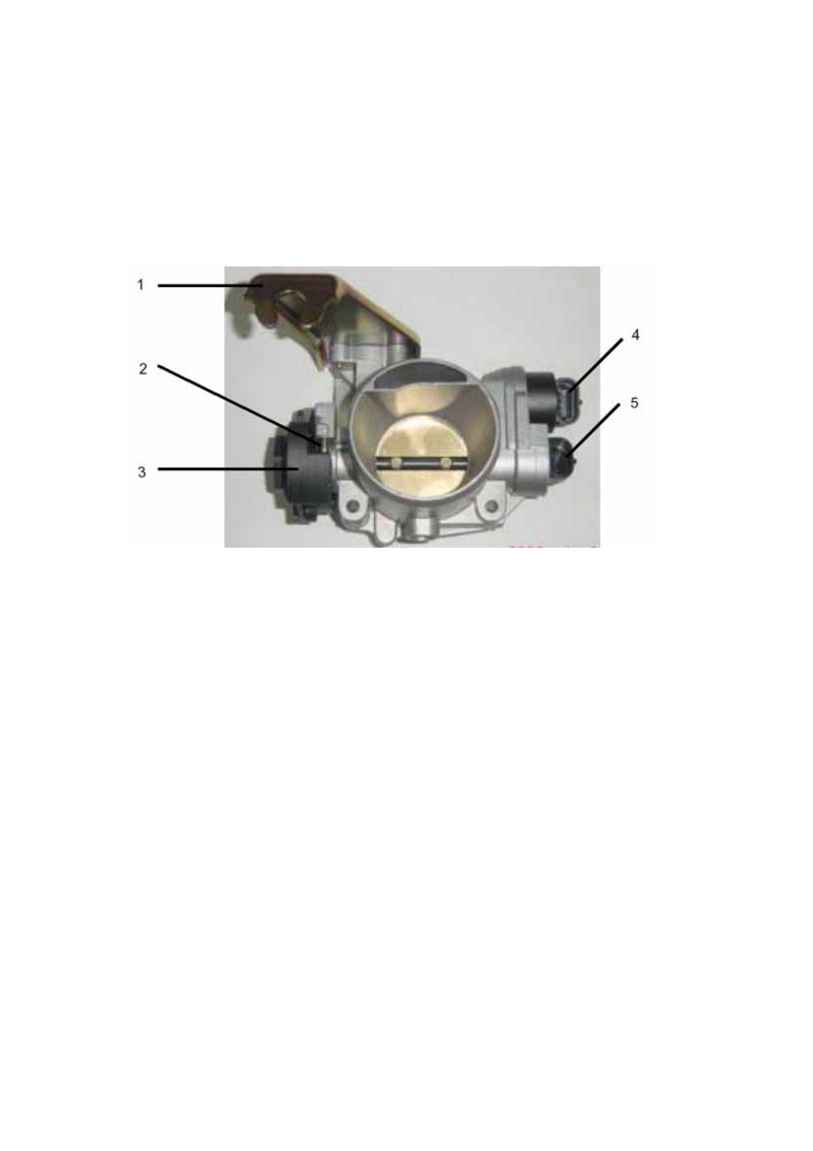
To avoid the mixture condensing and freezing in certain condition, throttle valve adjuster is 
supported by anti-deadlock screw to prevent it from completely closing, and heated by 
circulating coolant. Idling speed step motor (4) and throttle position sensor (5) are installed 
on throttle body.


1.Throttle Cable Supporter                       2.Anti-deadlock Screw      
3.Throttle Valve Opening Angle Control            4.Idling Speed Step Motor  
5.Throttle Position Sensor   
Remark: Do not loosen the screw because the anti-deadlock screw is locked by 
manufacturer during calibration of throttle valve. 


IDLE SPEED STEP MOTOR     

This kind of idling speed step motor (±25r/m) with high accuracy and good locating ability is 
used to control idle speed. Directly fixed on throttle body and composed of a step motor and a 
screw/worm retarder, it enables the lock pin (3) to convert the rotation motion into linear 
motion. When receiving control instruction from ECU, the step motor drive valve core 
moving (about 0.04mm/step) on axis direction through screw/worm device to change the 
bypass air intake volume of engine at idle, therefore the idle speed can be insured steady. The 
change is regulated based on the engine coolant temperature. 

Air intake efficiency of the engine at idle speed is demarcated based on opening of the 
throttle valve when by-pass air intake is closed through adjusting in manufacturing. 

Step motor is connected directly on throttle body by a fast clamp without fixing screw.


F-3


1.Idling Speed Step Motor     2. By-pass Hose     3. Lock Pin     4. Throttle Valve 

5. Throttle Body        6. ECU Electrical Control Unit       7.Steel Lock Ring 

Qo.    Air Leakage Volume Of Throttle 

Q.      By-pass Air Volume Of Step Motor


Specification: 

The coil resistance is R=53 ± 10Ω at 20℃. A max air intake volume will be got when the 
lock pin turns back 200 steps (approx 8mm stroke, correspond to about 60kg/h air intake 
volume). 

Working steps are determined according to the engine running condition, including heater 
opening and electrical load air condition opening etc. 

Batter terminal shall be disconnected for at least 5 minutes before inserting idling speed step 
motor into the throttle body. Accordingly, when the key opened, ECU will reset a new step 
motor and define steps according to the coolant temperature to adjust the valve core’s axial 
moving (forward or backward) with a correct idle speed. 

Electronic components can be diagnosed by engine ECU. Through regulating the throttle 
valve position, with engine speed and intake pressure signals, the engine ECU can detect 
whether the step motor (tested by a diagnosis tester) loses step or not.   


Recovery: 

If a failure happens, step motor will become invalid, correspondingly the adaptive function of 
air fuel ratio at idle is ceased.


F-4

THROTTLE POSITION SENSOR   

The sensor, including a potentiometer, the movable part of which is controlled by the throttle 
axis. ECU supplies a voltage approx. 5V to the potentiometer when working. 

From idling to throttle full open, oil injection process is administrated by parameters gained 
from throttle valve opening angle. 

ECU identifies whether the throttle is in the open or close position according to the output 
voltage and modifies the mixture ratio. When throttle closed, the voltage signal is transferred 
to ECU to confirm whether the engine is in idle or fuel cut-off state (differ from engine 
speed). 

Signals for throttle potentiometer need not adjusting because ECU software can automatically 
obtain the idle position (0-950mV) of throttle valve. 

Potentiometer is installed directly on throttle body and fixed with a fast snap ring. 


1.Connector   2.Resistance Circuit  3.Throttle Body   4.Throttle Valve Axis   5.Seat Snap Ring 

A – Ground Signal     B – 5V Voltage     C – Output Signal 


Recovery: 

If failure happens, the setting value is calculated through the readings of TDC (top dead 
center)/ ESS (engine speed sensor) and absolute pressure sensor. 

If there is a failure in the absolute pressure sensor signal, set throttle valve opening angle a 
fixed value 50 degree. For the moment, adopting the methods like buffering, idling 
adaptability and air fuel ratio adjustment all doesn’t work.. Throttle signal cycle is also 
malfunctioned when running automatic transmission.


F-5

INTEGRAL AIR PRESSURE/TEMPERATURE SENSOR 

Pressure signals are obtained from the voltage of one among four resistors in Wheatstone 
bridge marked on a special diaphragm. This diaphragm is compressed and stretched under 
the absolute pressure from inside of the manifolds (thus the above resistor is under pressure 
too). 

Air temperature sensor is a negative factor temperature sensor. So the higher the temperature 
is, the lower the resistance and the weaker the pressure signals will be.   

When a failure in sensor circuit happens, the air temperature is fixed at 45℃. 


Recovery: 

When a failure in sensor circuit happens, manifolds pressure value will be estimated 
according to the method of data-inserting arithmetic based on the rotate speed and related 
throttle valve opening angle in a pressure-recovery recorder Then the value shall be modified 
by coolant temperature and the air pressure.


Pins:  

1. Grounded 

2. Outputs Temperature Signal

3. 5V Power Source 

4. Outputs Pressure Signal 


F-6


Content   ..  20  21  22  23   ..