Acura RSX Honda Integra. Manual - part 311


  Index      Acura     Acura RSX Honda Integra - service repair manual 2002-2006 year


Search            


Content   ..  309  310  311  312   ..


Acura RSX Honda Integra. Manual - part 311


04

Standard: 0.04

0.12 mm (0.002

0.005 in.)

THRUST WASHER, 40 x 51.5 mm

No.

Part Number

Thickness

14-370

Shafts and Clutches

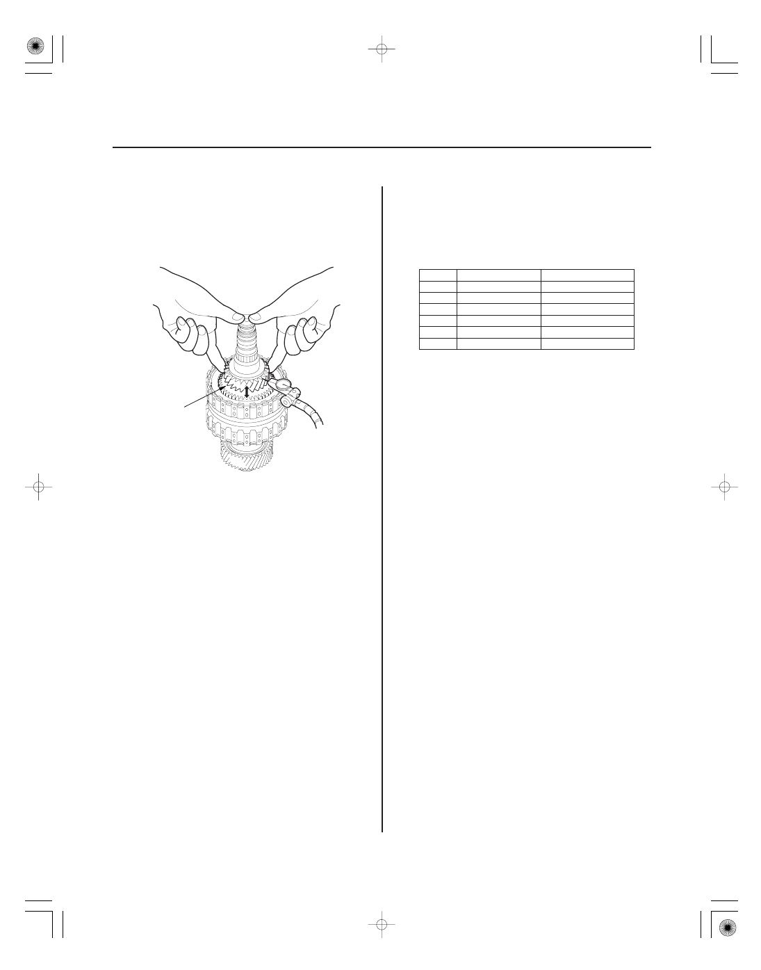
Secondary Shaft 1st Gear Clearance Inspection (cont’d)

A

5. Hold the secondary shaft, and measure the 1st gear

axial clearance in at least three places while
moving the 1st gear (A). Use the average as the
actual clearance.

6. If the clearance is out of standard, remove the 40 x

51.5 mm thrust washer and measure its thickness.

7. Select and install a new thrust washer, then

recheck.

1

90503-PRP-000

4.80 mm (0.189 in.)

2

90504-PRP-000

4.85 mm (0.191 in.)

3

90505-PRP-000

4.90 mm (0.193 in.)

4

90506-PRP-000

4.95 mm (0.195 in.)

5

90507-PRP-000

5.00 mm (0.197 in.)

6

90508-PRP-000

5.05 mm (0.199 in.)

8. After replacing the thrust washer, make sure the

clearance is within standard.

9. Disassemble the shaft and gears.

05/06/27 17:59:31 61S6M040_140_0371

01

S6M6A02E10410434071KDAT00

14-371

Idler Gear Shaft Removal and Installation

D

C

B

A

1. Remove the snap ring (A), cotter retainer (B), and

cotter keys (C). Do not distort the snap ring.

2. Remove the idler gear shaft/idler gear assembly (D)

from the transmission housing.

3. Check the snap rings and cotter retainer for wear

and damage. Replace them if they are worn,
distorted, or damaged.

4. Install the idler gear and shaft in the reverse order

of removal.

05/06/27 17:59:31 61S6M040_140_0372

01

01

03

02

S6M6A02E10410434065KBAT10

Special Tools Required

14-372

Shafts and Clutches

Idler Gear/Idler Gear Shaft Replacement

07749-0010000

07746-0010100

A

B

07749-0010000

07746-0010100

A

B

• Driver 07749-0010000
• Attachment, 32 x 35 mm 07746-0010100

1. Remove the snap ring from the idler gear/idler

shaft assembly.

2. Remove the idler gear shaft (A) from the idler gear

(B) with the special tools and a press.

3. Replace the idler gear or idler gear shaft, and attach

the idler gear shaft to the idler gear.

4. Install the idler gear shaft (A) in the idler gear (B)

with the special tools and a press.

5. Install the snap ring.

05/06/27 17:59:32 61S6M040_140_0373

01

01

02

03

S6M6A02E10411310041LCAT00

Special Tools Required

14-373

Clutch Disassembly

A

B

C

D

E

A

B

C

D

E

F

A

C

D

E

F

B

• Clutch spring compressor attachment

07LAE-PX40100 or 07HAE-PL50101

• Clutch spring compressor bolt assembly

07GAE-PG40200 or 07GAE-PG4020A

1. Remove the snap ring with a screwdriver.

2. Remove the clutch end plate (A), clutch discs (B) (4),

clutch waved-plates (C) (4), and waved spring (D)
from the 1st clutch drum (E).

3. Remove the clutch end plate (A), clutch discs (B) (4),

clutch waved-plates (C) (3), clutch flat-plate (D), and
waved spring (E) from the 2nd clutch drum (F).

4. Make a reference mark on the clutch flat plate (D).

5. Remove the clutch end plate (A), clutch discs (B) (4),

clutch waved-plates (C) (3), clutch flat-plate (D), and
waved spring (E) from the 3rd clutch drum (F).

6. Make a reference mark on the clutch flat plate (D).

(cont’d)

05/06/27 17:59:32 61S6M040_140_0374


Content   ..  309  310  311  312   ..