Acura RSX Honda Integra. Manual - part 237


  Index      Acura     Acura RSX Honda Integra - service repair manual 2002-2006 year


Search            


Content   ..  235  236  237  238   ..


Acura RSX Honda Integra. Manual - part 237


16

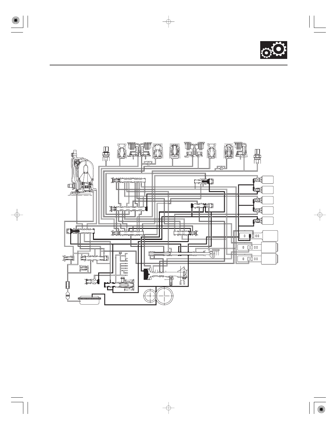
R Position: Shifting to R position from P or N position

14-73

TORQUE
CONVERTER

3RD CLUTCH
TRANSMISSION FLUID
PRESSURE
SWITCH

3RD
ACCUMULATOR

3RD
CLUTCH

1ST
CLUTCH

1ST
ACCUMULATOR

4TH
ACCUMULATOR

4TH
CLUTCH

5TH
CLUTCH 5TH

ACCUMULATOR

2ND
ACCUMULATOR

2ND
CLUTCH

2ND CLUTCH
TRANSMISSION FLUID
PRESSURE
SWITCH

30

30

95

30

10

95

10

40

40

50

20

95

20

20

91

90

94

LOCK-UP
SHIFT
VALVE

SHIFT
VALVE
C

SHIFT
VALVE
B

SHIFT
VALVE
A

10

3

4

X

57

SERVO CONTROL VALVE

SHIFT VALVE E

SHIFT
VALVE
D

ATF
COOLER

RELIEF VALVE

REGULATOR VALVE

SERVO VALVE

ATF PUMP

MANUAL VALVE

SHIFT
SOLENOID
VALVES

SA

A: OFF

B: ON

C: OFF

D: OFF

E: ON

A

B

C

X

X

X

X

X

SB
SC

SD
SE

55

X

1

X AX

56

X

4’’ X AX

57

4

X AX

X

A/T CLUTCH PRESSURE
CONTROL SOLENOID VALVES

1

1

1

50

X

X

X X

5A X X 56 5E

57

SC

X

SB

X

X

X X

X

X

SE

X

4

X

SD

X

X

X

X

X

X

X

X

X

55’

94

91

7

55

96 92

SE

4

5H

5B

5G

3C

5E

5C

5N

5L

5J

10

40

5F

50 30

1A

1B

55’

SA

3C

3’

3

5K

5K

20

5L

5J

1A

55’

57 X 1

93

90

93

90

96

92

55 97

93

95

7

99

92

95

1

1

3’

4’

4’’

3

7

1

4

93

5F

90

5H 5C

5B 5G

3B

3A

3A

X

1B

5A

5A

5N

TORQUE
CONVERTER
CHECK
VALVE

COOLER
CHECK
VALVE

LOCK-UP
CONTROL
VALVE

AX

HX

AX

HX

4’

IDLER
SHAFT

IDLER GEAR

MAINSHAFT

COUNTERSHAFT

FINAL DRIVE
GEAR
SECONDARY
SHAFT

3B 3A

When shifting in the R position, the PCM turns shift solenoid valves B and E ON, and A, C, and D OFF. Shift solenoid
valve B pressure (SB) is applied to the right side of the shift valve B, and shift valve B is moved to left side. Shift
solenoid valve E pressure (SE) is applied to the left side of shift valve E, and shift valve E is moved to the right side.
Line pressure (1) changes to (3) at the manual valve, and flows to the servo valve via the shift valve E. The servo valve
is moved to reverse range position. Movement of the shift valves B and E, and servo valve creates 4th clutch pressure
line between the 4th clutch and the A/T clutch pressure control solenoid valve A. The 4th clutch pressure (40) is
applied to the 4th clutch, and the 4th clutch is engaged gently.

NOTE: When used, ‘‘left’’ or ‘‘right’’ indicates direction on the hydraulic circuit.

(cont’d)

05/06/27 17:49:19 61S6M040_140_0074

17

Hydraulic Flow (cont’d)

R Position: Driving in reverse gear

Reverse Inhibitor Control

14-74

Automatic Transmission

System Description (cont’d)

TORQUE
CONVERTER

3RD CLUTCH
TRANSMISSION FLUID
PRESSURE
SWITCH

3RD
ACCUMULATOR

3RD
CLUTCH

1ST
CLUTCH

1ST
ACCUMULATOR

4TH
ACCUMULATOR

4TH
CLUTCH

5TH
CLUTCH 5TH

ACCUMULATOR

2ND
ACCUMULATOR

2ND
CLUTCH

2ND CLUTCH
TRANSMISSION FLUID
PRESSURE
SWITCH

30

30

95

30

10

95

10

40

40

50

20

95

20

20

91

90

94

LOCK-UP
SHIFT
VALVE

SHIFT
VALVE
C

SHIFT
VALVE
B

SHIFT
VALVE
A

10

3

4

X

57

SERVO CONTROL VALVE

SHIFT VALVE E

SHIFT
VALVE
D

ATF
COOLER

RELIEF VALVE

REGULATOR VALVE

SERVO VALVE

ATF PUMP

MANUAL VALVE

SHIFT
SOLENOID
VALVES

SA

A: ON

B: ON

C: OFF

D: OFF

E: ON

A

B

C

X

X

X

X

X

SB
SC

SD
SE

55

X

1

X AX

56

X

4’’ X AX

57

4

X AX

X

A/T CLUTCH PRESSURE
CONTROL SOLENOID VALVES

1

1

1

50

X

X

X X

5A X X 56 5E

57

SC

X

SB

X

X

X X

X

X

SE

X

4

X

SD

X

X

X

X

X

X

X

X

X

55’

94

91

7

55

96 92

SE

4

5H

5B

5G

3C

5E

5C

5N

5L

5J

10

40

5F

50 30

1A

1B

55’

SA

3C

3’

3

5K

5K

20

5L

5J

1A

55’

57 X 1

93

90

93

90

96

92

55 97

93

95

7

99

92

95

1

1

3’

4’

4’’

3

7

1

4

93

5F

90

5H 5C

5B 5G

3B

3A

3A

X

1B

5A

5A

5N

TORQUE
CONVERTER
CHECK
VALVE

COOLER
CHECK
VALVE

LOCK-UP
CONTROL
VALVE

AX

HX

AX

HX

4’

IDLER
SHAFT

IDLER GEAR

MAINSHAFT

COUNTERSHAFT

FINAL DRIVE
GEAR
SECONDARY
SHAFT

3B 3A

After starting off in reverse gear, the PCM turns shift solenoid valves A ON, and keeps B and E ON, and C and D OFF.
Shift solenoid valve A pressure (SA) is applied to the right side of shift valve A to cover the A/T clutch pressure control
solenoid valve A pressure port, and to uncover the line pressure port leading to the 4th clutch creating full line
pressure. The 4th clutch is engaged securely with line pressure.

While the vehicle is moving forward, the PCM keeps shift solenoid valve E remaining OFF. Shift valve E covers the port
of line pressure (3’) leading to the servo valve reverse position. The servo valve cannot be shifted to reverse position,
and hydraulic pressure is not applied to 4th clutch from servo valve for reverse; as a result, power is not transmitted to
the reverse direction.

NOTE: When used, ‘‘left’’ or ‘‘right’’ indicates direction on the hydraulic circuit.

05/06/27 17:49:20 61S6M040_140_0075

18

P Position

14-75

TORQUE
CONVERTER

3RD CLUTCH
TRANSMISSION FLUID
PRESSURE
SWITCH

3RD
ACCUMULATOR

3RD
CLUTCH

1ST
CLUTCH

1ST
ACCUMULATOR

4TH
ACCUMULATOR

4TH
CLUTCH

5TH
CLUTCH 5TH

ACCUMULATOR

2ND
ACCUMULATOR

2ND
CLUTCH

2ND CLUTCH
TRANSMISSION FLUID
PRESSURE
SWITCH

30

30

95

30

10

95

10

40

40

50

20

95

20

20

91

90

94

LOCK-UP
SHIFT
VALVE

SHIFT
VALVE
C

SHIFT
VALVE
B

SHIFT
VALVE
A

10

3

4

X

57

SERVO CONTROL VALVE

SHIFT VALVE E

SHIFT
VALVE
D

ATF
COOLER

RELIEF VALVE

REGULATOR VALVE

SERVO VALVE

ATF PUMP

MANUAL VALVE

SHIFT
SOLENOID
VALVES

SA

A: OFF

B: ON

C: OFF

D: OFF

E: ON

A

B

C

X

X

X

X

X

SB
SC

SD
SE

55

X

1

X AX

56

X

4’’ X AX

57

4

X AX

X

A/T CLUTCH PRESSURE
CONTROL SOLENOID VALVES

1

1

1

50

X

X

X X

5A X X 56 5E

57

SC

X

SB

X

X

X X

X

X

SE

X

4

X

SD

X

X

X

X

X

X

X

X

X

55’

94

91

7

55

96 92

SE

4

5H

5B

5G

3C

5E

5C

5N

5L

5J

10

40

5F

50 30

1A

1B

55’

SA

3C

3’

3

5K

5K

20

5L

5J

1A

55’

57 X 1

93

90

93

90

96

92

55 97

93

95

7

99

92

95

1

1

3’

4’

4’’

3

7

1

4

93

5F

90

5H 5C

5B 5G

3B

3A

3A

X

1B

5A

5A

5N

TORQUE
CONVERTER
CHECK
VALVE

COOLER
CHECK
VALVE

LOCK-UP
CONTROL
VALVE

AX

HX

AX

HX

4’

IDLER
SHAFT

IDLER GEAR

MAINSHAFT

COUNTERSHAFT

FINAL DRIVE
GEAR
SECONDARY
SHAFT

3B 3A

Shift solenoid valves B and E are turned ON, and A, C, and D are turned OFF by the PCM. Line pressure (1) flows to the
shift solenoid valves and A/T clutch pressure control solenoid valve A. Line pressure (3) changes to (3’) at shift valve E,
and flows to the servo valve. The servo valve is moved to reverse/park position. Hydraulic pressure is not applied to
the clutches.

05/06/27 17:49:21 61S6M040_140_0076

01

*01

S6M6A02E10474000000CAAT06

Lock-up System

Torque Converter Clutch Lock-up ON (Engaging Torque Converter Clutch)

Torque Converter Clutch Lock-up OFF (Disengaging Torque Converter Clutch)

14-76

Automatic Transmission

System Description (cont’d)

Power flow

The power flows by way of:

Engine

Drive plate

Torque converter cover

Torque converter clutch piston

Damper spring

Turbine

Mainshaft

MAINSHAFT

TURBINE

DAMPER SPRING

TORQUE CONVERTER
CLUTCH PISTON

TORQUE CONVERTER
COVER

To ATF cooler

INLET

OUTLET

MAINSHAFT

TURBINE

TORQUE CONVERTER
COVER

PUMP

To ATF cooler

INLET

Power flow

The power flows by way of:

Engine

Drive plate

Torque converter cover

Pump

Turbine

Mainshaft

STATOR

The lock-up mechanism of the torque converter clutch operates in D position (2nd, 3rd, 4th, and 5th), and in D3
position (2nd and 3rd), and M (sequential sportshift mode) position (3rd, 4th, and 5th). The pressurized fluid is drained
from the back of the torque converter through a fluid passage, causing the torque converter clutch piston to be held
against the torque converter cover. As this takes place, the mainshaft rotates at the same speed as the engine
crankshaft. Together with the hydraulic control, the PCM optimizes the timing and amount of the lock-up mechanism.
When the shift solenoid valve E is turned on by the PCM, shift solenoid valve E pressure switches the lock-up shift
valve lock-up on and off. The A/T clutch pressure control solenoid valve A and the lock-up control valve control the
amount of the lock-up.

Fluid in the chamber between the torque converter cover and the torque converter clutch piston is drained off, and
fluid entered from the chamber between the pump and stator exerts pressure through the torque converter clutch
piston against the torque converter cover. The torque converter clutch piston engages with the torque converter cover;
the torque converter clutch lock-up is ON, and the mainshaft rotates at the same speed as the engine.

Fluid entering from the chamber between the torque converter cover and the torque converter clutch piston passes
through the torque converter and goes out from the chambers between the turbine and the stator, and between the
pump and the stator. As a result, the torque converter clutch piston moves away from the torque converter cover, and
the torque converter clutch lock-up is released; torque converter clutch lock-up is OFF.

05/06/27 17:49:22 61S6M040_140_0077


Content   ..  235  236  237  238   ..