Acura RSX Honda Integra. Manual - part 220


  Index      Acura     Acura RSX Honda Integra - service repair manual 2002-2006 year


Search            


Content   ..  218  219  220  221   ..


Acura RSX Honda Integra. Manual - part 220


04

06

03

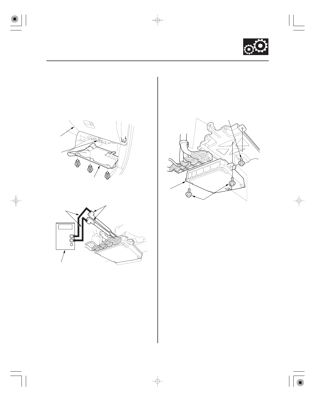
How to Troubleshoot Circuits at the PCM

How to Remove and Install the PCM

Special Tools Required

14-5

B

C

A

C

B
07SAZ-01000A

A
07SAZ-01000A

B

C
6 x 1.0 mm
12 N·m (1.2 kgf·m, 8.7 lbf·ft)

A
6 x 1.0 mm
12 N·m (1.2 kgf·m, 8.7 lbf·ft)

Backprobe set 07SAZ-001000A (two required)

1. Remove the dashboard lower cover (A) under the

glove box (B), then you can see the PCM
connectors (C).

2. Connect the backprobe adapters (A) to the stacking

patch cords (B), and connect the cords to a
multimeter (C).

3. Using the wire insulation as a guide for the

contoured tip of the backprobe adapter, gently slide
the tip into the connector from the wire side until it
touches the end of the wire terminal.

4. If you cannot get to the wire side of the connector

or the wire side is sealed, disconnect the connector
and use the tester probe to probe the connectors
from the terminal side. Do not force the probe into
the connector.

1. Remove the dashboard lower cover from under the

glove box.

2. Disconnect PCM connectors.

3. Loosen the bolt (A) on the back of the PCM (B), and

remove the two bolts (C) and PCM.

4. Install the PCM in the reverse order of the removal.

(cont’d)

05/06/27 17:48:15 61S6M040_140_0006

01

09

PCM Reset Procedures

How to End a Troubleshooting Session

14-6

Automatic Transmission

General Troubleshooting Information (cont’d)

A

A

B

NOTE: After resetting the PCM, do the PCM idle learn
procedure (see page 11-349).

1. Turn the ignition switch OFF.

2. Use one of these methods to reset the PCM

memory.

• Use the Scan Tool or the HDS to the DLC (A).

• Remove the No. 6 ECU fuse (A) in the under-hood

fuse/relay box (B) for more than 10 seconds.

This procedure must be done after any troubleshooting.

1. Turn the ignition switch OFF.

2. Reset the PCM using one of these methods:

• Use the Scan Tool or the HDS, then disconnect

the Scan Tool or the HDS from the DLC.

• Disconnect the Scan Tool or the HDS from the

DLC, then reset the PCM by removing the No. 6
ECU fuse in the under-hood relay/fuse box for
more than 10 seconds.

NOTE: After resetting the PCM, do the PCM idle
learn procedure (see page 11-349).

3. To verify that the problem is repaired, test-drive the

vehicle for several minutes at speeds over 30 mph
(50 km/h) or in freeze data range.

05/06/27 17:48:15 61S6M040_140_0007

02

PCM Updating and Substitution for Testing

How to Update the PCM

How to Substitute the PCM

Special Tools Required

14-7

A

Honda Interface Module (HIM) EQS05A35570

Use this procedure when you have to substitute a
known-good PCM in a troubleshooting procedure.
Update the PCM only if the PCM does not already have
the latest software loaded.

NOTE: Do not turn the ignition switch OFF while
reprogramming the PCM. If you turn the ignition switch
OFF, the PCM can be damaged.

1. Turn the ignition switch ON (II). Do not start the

engine.

2. Connect the Honda Interface Module (HIM) to the

Data Link Connector (DLC) (A) located under the
driver’s side of dashboard.

3. Do the PCM update procedure as described on the

HIM label and in the PCM update system. If the
software in the PCM is the latest version, substitute
the PCM.

1. Remove the PCM from the vehicle.

2. Install a known-good PCM in the vehicle.

3. Rewrite the immobilizer code with the PCM

replacement procedure on the HDS. It allows you to
start the engine.

4. After completing your tests, reinstall the original

PCM and rewrite the immobilizer code with the
PCM replacement procedure on the HDS again.

05/06/27 17:48:15 61S6M040_140_0008

01

01

S6M6APPK77100000000BBAT20

2005-2006 Models

How to Check for DTCs with the Honda
Diagnostic System

Symptom Troubleshooting Versus DTC
Troubleshooting

14-8

Automatic Transmission

General Troubleshooting Information (cont’d)

B

A

A

When the powertrain control module (PCM) senses an
abnormality in the input or output systems, the D
indicator (A) in the gauge assembly (B) will usually
blink.

When the Honda diagnostic system (HDS) is connected
to the data link connector (DLC) (A) (located under the
dash behind the center console), it will indicate the
diagnostic trouble code (DTC) when the ignition switch
is turned ON (II) and appropriate menu is selected.

If the D indicator or malfunction indicator lamp (MIL)
has been reported on, or if a driveability problem is
suspected, follow this procedure:

1. Connect the HDS to the DLC. (See the HDS user’s

manual for specific instructions.)

2. Turn the ignition switch ON (II), select A/T system,

and observe the DTC in the DTCs MENU on the
HDS screen.

3. Record all fuel and emissions DTCs, A/T DTCs, and

freeze data.

4. If there is a fuel and emissions DTC, first check the

fuel and emissions system as indicated by the DTC.
(except for DTC P0700, DTC P0700 means there is
one or more A/T DTCs, and no problems were
detected in the fuel and emissions circuit of the
PCM).

5. Clear the DTC and data.

6. Drive the vehicle for several minutes under the

same conditions as those indicated by the freeze
data, and then recheck for a DTC. If the A/T DTC
returns, go to the DTC troubleshooting index. If the
DTC does not return, there was an intermittent
problem within the circuit. Make sure all pins and
terminals in the circuit are tight.

Some symptoms will not trigger diagnostic trouble
codes (DTCs) or cause the D indicator to blink. If the
malfunction indicator lamp (MIL) was reported on or
the D indicator has been blinking, check for DTCs. If the
vehicle has an abnormal symptom, and there are no
DTCs stored, go to the symptom troubleshooting index.
Check the list of probable cause(s) for the symptom, in
the sequence listed, until you find the problem.

05/06/27 17:48:16 61S6M040_140_0009


Content   ..  218  219  220  221   ..