Acura RSX Honda Integra. Manual - part 22
*01
S6M6AZHA26100000000EAAT00
2005-2006 Models
4-24
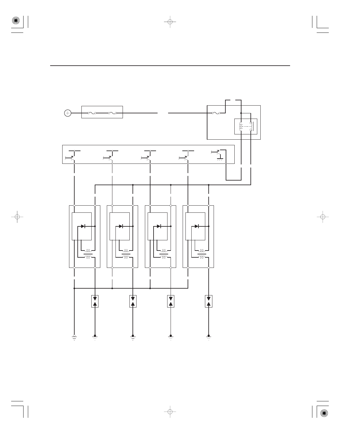
Ignition System
Circuit Diagram (cont’d)
No. 6 (20 A)
BATTERY
UNDER-HOOD FUSE/RELAY BOX
No. 19 (100 A)
IGNITION
COIL
RELAY
No. 31 (15 A)
BLK/WHT
YEL/GRN
BLK/WHT
BLK
No. 1
BLK
BLK/WHT
BLU/RED
No. 2
No. 4
BRN
BLK/WHT
ICM
BLK
BLK
BLK/WHT
WHT/BLU
No. 3
ICM: Ignition Control Module
ECM/PCM
G101
ICM
ICM
ICM
IGPLS4
1
3
2
RED/YEL
BLU
UNDER-DASH
FUSE/RELAY
BOX
BLU
MRLY
4
1
3
2
IGNITION
COILS
SPARK
PLUGS
5V
IGPLS3
IGPLS2
IGPLS1