Acura RL (1996-2004 year). Manual - part 645
 

  Index      Acura     Acura RL 1996-2004 year - service repair manual


Search            


Content   ..  643  644  645  646   ..


Acura RL (1996-2004 year). Manual - part 645


Multiplex Control System

Power and Ground Test (cont'd)

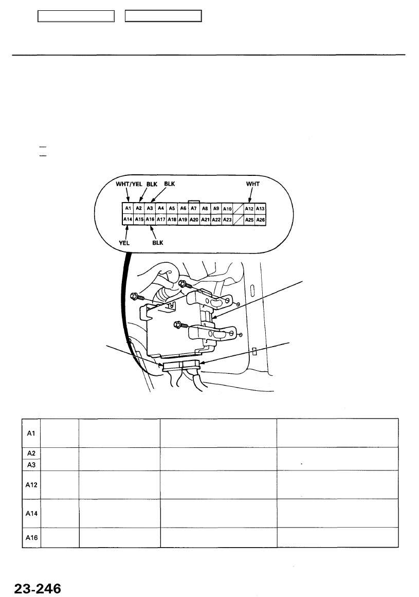
Multiplex Control Unit (Passenger's):

1. Remove the right kick panel (see 

section 20

).

2. Disconnect the 22P and 26P connectors, then remove the passenger's unit.
3. Inspect the connector and socket terminals to be sure they are all making good contact.

• If the terminals are bent, loose or corroded, repair them as necessary, and recheck the system.
• If the terminals look OK, make the following input tests at the connector.

If a test indicates a problem, find and correct the cause, then recheck the system.
If all the input tests prove OK, the control unit must be faulty; replace it.

Wire side of
female terminals

26P CONNECTOR

MULTIPLEX CONTROL UNIT (PASSENGER'S)

22P CONNECTOR

Cavity Wire Test condition Test: Desired result Possible cause if result is not obtained

Under all conditions

Under all conditions

Under all conditions

Ignition switch ON (II)

Under all conditions

WHT/YEL

BLK

WHT

YEL

BLK

Check for voltage to ground:
There should be battery voltage.

Check for continuity to ground:
There should be continuity.

Check for voltage to ground:
There should be battery voltage.

Check for voltage to ground:
There should be battery voltage.

Check for continuity to ground:
There should be continuity.

• Blown No. 56 (7.5 A) fuse in the

under-hood fuse/relay box

• An open in the wire

• Poor ground (G401, G402)
• An open in the wire

• Blown No. 44 (20 A) fuse in the

under-hood fuse/relay box

• An open in the wire

• Blown No. 13 (7.5 A) fuse in the

under-dash fuse/relay box

• An open in the wire

• Poor ground (G404)
• An open in the wire

Main Menu

Table of Contents

Multiplex Control Unit (Driver's):

1. Remove the under-dash fuse/relay box (see page 

23-66

).

2. Remove the driver's unit from the under-dash fuse/relay box.
3. Inspect the connector and socket terminals to be sure they are all making good contact.

• If the terminals are bent, loose or corroded, repair them as necessary, and recheck the system.
• If the terminals look OK, make the following input tests at the connector and the fuse/relay box socket.

— If any test indicates a problem, find and correct the cause, then recheck the system.
— If all the input tests prove OK, the control unit must be faulty; replace it.

Wire side of
female terminals

MULTIPLEX CONTROL UNIT (DRIVER'S)

16P

CONNECTOR

26P CONNECTOR

*2: Canada

Cavity Wire Test condition Test: Desired result Possible cause if result is not obtained

Under all conditions

Under all conditions

Ignition switch ON (II)

Check for voltage to ground:
There should be battery voltage.

Check for continuity to ground:
There should be continuity.

Check for voltage to ground:
There should be battery voltage.

Fuse/relay

box socket

• Blown No. 56 (7.5 A) fuse in the

under-hood fuse/relay box

• An open in the wire

• Poor ground (G401, G402 or G251)
• An open in the wire

• Blown No. 13 (7.5 A) fuse in the

under-dash fuse/relay box

• Faulty under-dash fuse/relay box

A13

A8

A7

Wire side of
female terminals

Main Menu

Table of Contents

Multiplex Control System

Self-diagnosis Function (Mode 1)

• 1 second after you go into self-diagnosis function mode 1, the function starts to indicate the diagnosis trouble code

(DTC), and repeats the DTC every 3 seconds.

• From mode 1, disconnect the SCS service connector for 5 to 10 seconds, then reconnect the SCS service connector,

and the function goes from mode 1 to mode 2.

Normal conditions (Ignition
switch OFF)

Connect the SCS service connec-

tor to the multiplex control inspec-
tion connector for more than 5

seconds.

The system is OK.

NO

*Does the ignition key light and

buzzer come ON?

YES

MULTIPLEX CONTROL
INSPECTION CONNECTOR

Go to self-diagnosis function mode

1 (see page 

23-248

).

NOTE: If no DTCs are indicated, but you know the system is abnormal, check these items:
• If the light does not come on and the buzzer does not beep, check the continuity between the BLK wire of the multiplex

control inspection connector and body ground.

• If either the light or the beep indicates the DTC(s), check the continuity between the PNK/BLK wire of the multiplex

control inspection connector and multiplex control units (driver's and passenger's).

Diagnostic Trouble Code (DTC) Table

NOTE: The numbers in the table show the troubleshooting sequence.

Main Menu

Table of Contents

+

BODY

Communication Line Test

1. Continuity Test

Check for continuity according to the table.
• If there is continuity, go to step 2.
• If there is no continuity, check for an open in the wire.

2. Voltage Test

A. Turn the ignition switch ON (II).

B. Check for voltage between communication line and ground:

The voltage should match the following table.

• If the voltage is too high:

A. Check for short to another wire.

B. Check for poor contact at the connector on the receiver side unit.
C. Faulty circuit in the receiver side unit.

• If the voltage is too low:

A. Check for short to ground or to another wire.

B. Check for poor contact at the connector on the transmit side unit.
C. Faulty circuit in the transmitter side unit.

* If any control units appears to be faulty, select one control unit, substitute a known-good control unit, then recheck. If the

system works properly, the original control unit is faulty; replace it. If there is still a malfunction, a substitute the known-
good control unit for another control unit, then recheck. If the system works properly, that control unit is faulty; replace

it.

Main Menu

Table of Contents


Content   ..  643  644  645  646   ..